3295 Cobb International Blvd. Kennesaw, GA 30152 800-367-1377 sale@patiostools.com

Product Variation:

10 Tips for Choosing Grounding Accessories?

Choosing the right Grounding Accessories is not a minor purchasing decision. It affects electrical safety, equipment reliability, inspection results, and long-term maintenance costs. A grounding clamp may look simple, yet its material, pressure rating, corrosion resistance, and installation method can determine whether a fault current travels safely. Small details matter.

Mike Holt, a respected electrical training expert, explains, “The purpose of grounding is to limit the voltage imposed by lightning, line surges, or unintentional contact with higher-voltage lines.” This principle gives our guide a practical direction. The best accessory is not always the cheapest or the most familiar. It must match the conductor, grounding electrode, environment, and expected fault conditions. A copper connection near coastal air needs different protection from one installed in a dry indoor room. That difference is easy to overlook.

This guide presents 10 Tips for Choosing Grounding Accessories, based on installation experience, recognized electrical practices, and careful product evaluation. We will examine clamps, bonding jumpers, connectors, inspection points, and corrosion protection. We will also consider certification, compatibility, current capacity, and installation guidance. Some choices may still require professional judgment. No checklist can replace a site assessment.

That is worth admitting.

Product labels can be confusing. Marketing claims can sound stronger than test evidence. Even experienced buyers sometimes focus on price before lifecycle performance. A better approach checks measurable specifications, manufacturer documentation, and local technical requirements. Safe grounding depends on the complete system, not one impressive-looking component.

10 Tips for Choosing Grounding Accessories?

Understanding Grounding Accessories and Their Safety Role

10 Tips for Choosing Grounding Accessories

Understanding Grounding Accessories and Their Safety Role

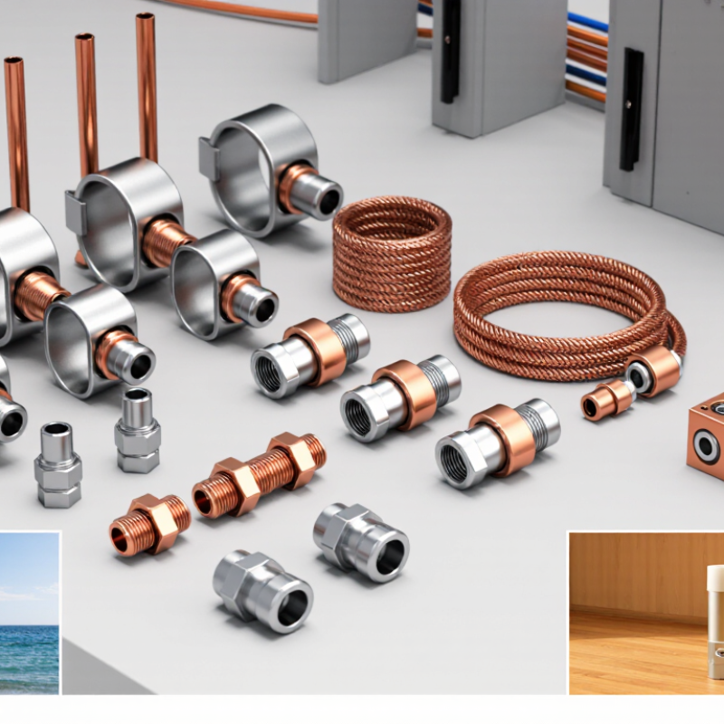
Grounding accessories help direct fault current safely toward earth. They include clamps, bonding jumpers, lugs, grounding bars, and electrode connectors. Each part supports electrical continuity. A loose connection can create heat, sparks, or dangerous touch voltage. Choose accessories made for the conductor material, installation environment, and expected fault conditions. Corrosion resistance matters near soil, moisture, chemicals, and outdoor equipment. Check technical ratings, installation instructions, and applicable electrical codes before purchasing.

Tip 1: Match the connector to the conductor size and type. Copper and aluminum require different contact methods.

Tip 2: Inspect the contact surface. It should be clean, stable, and free from damaging oxidation.

Tip 3: Select hardware suitable for indoor or outdoor exposure.

Tip 4: Confirm that clamps fit the grounding electrode securely. A poor fit may look acceptable but fail during stress.

Tip 5: Use listed components from reliable suppliers, with clear test information and traceable specifications.

Installation quality is equally important. Tighten connections to the manufacturer’s stated torque, not guesswork. Protect buried connections against moisture and soil movement. Keep bonding paths short, direct, and mechanically protected. A qualified electrician should verify continuity and inspect unusual installations. Testing may reveal a hidden weakness. Even experienced workers can overlook one small connection. I would also photograph completed joints before covering them, because later inspection becomes difficult. Safety depends on the entire grounding path, not one impressive-looking accessory.

Identifying Site Conditions and Grounding System Requirements

10 Tips for Choosing Grounding Accessories

Identifying site conditions is the real starting point for selecting grounding accessories. Soil changes dramatically between wet clay, dry sand, rock, and chemically treated ground. A copper rod that performs well near a damp foundation may underperform in rocky soil. Inspectors should record soil type, moisture, temperature, buried utilities, and available installation depth. Small details matter.

The grounding system must match the fault-current path, equipment voltage, and local electrical rules. NFPA 70, Article 250.4, requires an effective path for ground-fault current. OSHA safety guidance estimates that electrical hazards cause about 300 worker deaths and 4,000 injuries annually in the United States. These figures make connection quality more than a design preference. Check conductor size, clamp compatibility, corrosion exposure, and mechanical strength. A loose connection can look acceptable.

IEEE Std 142 explains that one resistance target cannot suit every installation. Measure the site instead of copying a previous project. Soil resistivity testing can reveal whether additional electrodes, deeper installation, or bonding improvements are needed. IEC 60364-4-41 also links protective disconnection to the installation’s earthing arrangement. Field experience teaches an uncomfortable lesson: drawings may not reflect buried conditions. Recheck assumptions after excavation. I have seen tidy systems fail because the soil was never tested. That mistake is preventable.

10 Tips for Choosing Grounding Accessories? - Identifying Site Conditions and Grounding System Requirements

No. Site Condition Suitable Grounding Accessories Selection Requirement Verification Method
1 Soil Resistivity Determine how easily fault current can disperse through the soil. Soil resistivity is commonly measured in ohm-metres using a field test. Ground rods, tape electrodes, buried ring conductors, inspection pits and test links. Use a larger or longer electrode system, or multiple bonded electrodes, where high-resistivity soil makes the target resistance difficult to achieve. Final electrode layout should be based on measured results and the applicable electrical code. Four-point soil-resistivity testing and post-installation earth resistance testing.
2 Available Fault Current Review the prospective fault current, protective-device clearing time and the thermal withstand requirement of the grounding conductors. Main grounding conductors, bonding jumpers, compression connectors, mechanical clamps and grounding bars. Size conductors and connectors for the expected fault duty and installation environment. Connections must remain mechanically secure until protective devices clear the fault. Short-circuit study, conductor sizing review and visual inspection of connections.
3 Electrode Material and Compatibility Identify the electrode material and check for galvanic or chemical interaction between dissimilar metals. Listed clamps, exothermic or irreversible compression connections, bimetallic connectors and compatible grounding bars. Use connectors specifically approved for the electrode and conductor materials. Avoid direct contact between incompatible metals unless a suitable transition connector is provided. Material certificates, connector markings and installation inspection.
4 Corrosive Soil or Chemical Exposure Check soil pH, salt content, industrial chemicals, wastewater exposure and areas subject to persistent moisture. Corrosion-resistant conductors, sealed inspection pits, protective coatings and compatible corrosion-resistant clamps. Select materials and coatings appropriate for the measured or documented exposure. Do not rely on coatings where the connection must maintain a permanent low-impedance path unless the connection method is approved for that use. Environmental assessment, periodic visual inspection and continuity testing.
5 Rocky, Shallow or Congested Ground Identify drilling restrictions, buried utilities, foundations, underground services and the depth of usable soil. Horizontal counterpoise conductors, ground plates, multiple shorter electrodes, bonding conductors and accessible test points. Adapt the electrode geometry to the available area while maintaining safe separation from utilities. Coordinate the layout with civil and electrical drawings before excavation. Utility-location survey, installation records and resistance testing.
6 Frost, Dry Seasons and Seasonal Moisture Consider seasonal changes in soil moisture and the local frost depth, because frozen or very dry soil can increase measured resistance. Deep-driven electrodes, buried ring conductors, protected test wells and flexible bonding connections. Place electrodes below the local frost-affected zone where practical and account for seasonal soil conditions in the design. Do not use temporary watering as a permanent grounding solution. Seasonal resistance measurements and review of local geotechnical conditions.
7 Lightning and Surge Exposure Determine whether the structure includes lightning protection, overhead lines, sensitive electronics or frequent surge exposure. Short, straight bonding conductors, equipotential bonding bars, test joints, lightning down-conductor connectors and surge protective device bonding conductors. Minimize conductor length and sharp bends, bond metallic systems where required, and coordinate the grounding arrangement with the lightning and surge-protection design. Visual routing inspection, continuity testing and review of bonding details.
8 Equipotential Bonding Needs Identify exposed conductive parts, structural steel, metallic piping, cable trays, tanks and other systems that may introduce different touch potentials. Equipotential bonding bars, bonding clamps, flexible braids, bonding jumpers and labeled test links. Bonding conductors should be routed and sized according to the governing code and fault conditions. Connections must be accessible where inspection or testing is required. Continuity testing between bonded parts and inspection of conductor routing.
9 Mechanical Damage and Accessibility Assess vehicle traffic, construction activity, vibration, impact risk, public access and the likelihood of unauthorized disturbance. Protective conduits, guarded ground bars, recessed inspection pits, lockable covers and strain-relief fittings. Protect exposed conductors and connections from impact, abrasion and unauthorized access while keeping test points reachable for qualified personnel. Physical inspection, cover and enclosure checks, and torque verification where specified.
10 Testing, Documentation and Maintenance Confirm that the system can be isolated, tested and maintained without compromising permanent protective bonding. Removable test links, labeled grounding bars, inspection chambers, permanent identification tags and test terminals. Provide clear records of electrode locations, conductor sizes, connection methods and test results. Use qualified personnel and follow the applicable local electrical and safety requirements. Continuity, earth resistance and, where applicable, clamp or fall-of-potential testing with documented results.

Evaluating Materials, Sizes, Compatibility, and Durability

Choosing grounding accessories requires more than matching a connector to a cable. Material matters. Copper offers excellent conductivity, while galvanized steel can provide stronger mechanical protection in harsh environments. Tip: Check corrosion resistance first. The U.S. Bureau of Labor Statistics recorded 145 fatal occupational injuries involving electricity exposure in 2022. Reliable grounding hardware deserves serious inspection.

Tip: Measure conductor size carefully. Tip: Confirm the system voltage. Accessories should match the installation’s conductor material, cross-section, and connection method. IEC 62561 addresses requirements for lightning protection system components, including mechanical strength and corrosion behavior. UL 467 also evaluates grounding and bonding equipment for electrical safety. These references help, but field conditions can still expose weak choices. I have seen a connector fit physically yet fail because its plating was unsuitable for moisture.

Tip: Verify compatibility before purchase. Tip: Inspect contact surfaces. Tip: Select certified components. Tip: Review temperature ratings. Tip: Test continuity after installation. Tip: Avoid mixing incompatible metals. Tip: Check tightening torque. Tip: Keep inspection records. Tip: Replace damaged hardware promptly. NETA maintenance guidance supports documented testing, visual inspection, and resistance measurements for electrical systems. However, a low reading does not prove permanent reliability. Loose fasteners, vibration, water, and soil chemistry can change performance later. Tip: Schedule follow-up inspections after severe weather or equipment movement.

Checking Standards, Installation Methods, and Maintenance Needs

Choosing grounding accessories requires more than matching sizes and prices. Check the standards required for your project, including electrical safety rules and local installation codes. Confirm that clamps, conductors, rods, and bonding parts have suitable test documentation. A certificate alone is not enough. Its scope and date should match the application.

Tip: Ask an experienced installer to inspect the connection points before purchase. Consider soil type, moisture, temperature, and corrosion exposure. A rod suitable for dry soil may perform poorly near coastal areas. Select compatible metals to reduce galvanic corrosion. I once saw a connection loosen because the hardware looked correct but did not fit the conductor properly. Small details matter.

Installation methods should match the design and site conditions. Follow the specified torque, burial depth, separation distance, and bonding route. Keep joints accessible when possible. After installation, measure resistance with appropriate testing equipment and record the results. Do not rely only on visual checks. Maintenance needs should be practical, not theoretical. Schedule inspections after severe weather and during planned electrical servicing. Look for rust, loose fasteners, damaged insulation, and water entry. Records may seem tedious, but they reveal gradual performance changes. Some maintenance plans still need improvement after real-world use.

Comparing Suppliers, Costs, Certifications, and Product Support

Choosing grounding accessories requires more than comparing unit prices. NFPA’s Home Fires Involving Electrical Distribution and Lighting Equipment report estimated 28,900 fires annually in the United States from 2016 to 2020. These incidents caused about 440 civilian deaths and $1.3 billion in property damage. Grounding parts are small, but their failure can become expensive.

Compare suppliers by traceability, not only quotations. Request material certificates, batch numbers, test records, and installation instructions. Check whether lugs, clamps, rods, and bonding conductors match applicable requirements, such as UL 467 or IEC 62561. Certification marks should be verifiable through an official database.

A low-cost clamp may hide higher labor costs if its plating is inconsistent or its torque guidance is unclear. That mistake is easy to make.

Support matters in the field. Ask whether engineers can review soil conditions, conductor sizes, corrosion risks, and inspection photos. The International Electrotechnical Commission’s IEC 60364 framework emphasizes protective measures, verification, and continuity, not a single accessory.

Compare replacement times, warranty terms, training, and documentation languages. Price the whole installation: product, freight, testing, rework, and future inspection.

I have seen purchasing teams overvalue a five-percent discount. They sometimes overlook missing test data. That deserves a second look.