
Choosing the right 3 Phase Brushless Dc Motor requires more than comparing rated power and price. Engineers must examine torque, speed range, efficiency, thermal limits, control method, and operating environment. A motor running inside a compact pump faces different demands from one driving a robotic joint. Small details matter, including winding resistance, bearing quality, encoder accuracy, and cooling airflow.
Market evidence shows why careful selection matters. Grand View Research reported that the global brushless DC motor market reached approximately USD 20.9 billion in 2023. It also projected strong growth through 2030, supported by electric vehicles, industrial automation, appliances, and medical equipment. MarketsandMarkets has similarly identified transportation and factory automation as major growth areas. These reports indicate opportunity, but they do not choose the motor for you. Application data still matters most.
Dr. Thomas A. Lipo, a respected electric-machine researcher, emphasizes that “the motor and its power converter must be treated as one system.” That principle is easy to overlook. A highly efficient motor can perform poorly with an unsuitable controller, weak feedback, or inadequate heat removal. This guide will compare motor construction, electrical ratings, control strategies, and supplier evidence. It will also question common assumptions. Maximum efficiency is not always the best target. A slightly larger motor may deliver quieter operation, longer service life, and safer thermal performance. The perfect specification rarely exists. A practical choice balances measurable performance with real operating conditions.
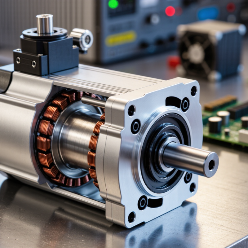
Choosing the best 3-phase brushless DC motor starts with understanding its internal structure. The stator contains three sets of copper windings arranged around a laminated iron core. The rotor carries permanent magnets and rotates inside the stator. There are no brushes to wear against a commutator. This reduces mechanical friction and maintenance.
An electronic controller energizes the three phases in a timed sequence. The energized winding creates a magnetic field, which pulls and pushes the rotor magnets forward. Hall sensors can report rotor position to the controller. Sensorless systems estimate position from back electromotive force. Six-step commutation is common, although advanced control can produce smoother torque.
The motor may look simple. Its timing is not.
When selecting a motor, match its voltage, continuous torque, peak torque, speed range, and cooling conditions to the application. Check the winding resistance and inductance, because both affect heat and controller response. A motor rated for high speed may provide disappointing torque at low speed. Heat changes everything. In bench testing, I would measure temperature near the winding housing, not only at the outer case. I initially trusted advertised efficiency figures too quickly; they often depend on load, speed, and test conditions. Mechanical inertia, duty cycle, noise, and encoder requirements also deserve attention. A slightly oversized motor can run cooler, but excessive size may waste space and increase startup current.

How to Choose the Best 3 Phase Brushless DC Motor
Defining motor requirements starts with speed, torque, and power. A motor should match the real load, not an ideal spreadsheet. The U.S. Department of Energy’s Industrial Motor Systems Market Opportunities Assessment estimates that motor-driven equipment uses about 68% of industrial electricity. Efficiency matters. For a rotating load, mechanical power equals torque multiplied by angular speed. For example, 2 N·m at 3,000 rpm requires about 628 W of mechanical power. Add losses, acceleration demand, and a realistic service margin. Do not size only by rated power. A conveyor may need modest running torque, yet demand much higher torque during startup. That moment often exposes a poor selection.
Measure the load profile over time. Record continuous torque, peak torque, operating speed, duty cycle, and shaft inertia. A three-phase BLDC motor also needs a compatible controller, voltage range, current capacity, and commutation feedback. Hall sensors can simplify low-speed starting, while sensorless control may struggle under heavy startup loads. The International Energy Agency’s Energy Efficiency 2023 report emphasizes the importance of efficient electric motor systems across industry. Thermal conditions still deserve attention. In a confined enclosure, even a correctly rated motor can overheat. A practical check is simple: compare the required RMS current with the motor’s continuous rating, then verify peak duration. One assumption may be wrong. Recheck it. Finally, confirm speed regulation, noise, braking needs, and installation space before approving the motor.
How to Choose the Best 3 Phase Brushless DC Motor
Comparing Electrical, Mechanical, and Thermal Specifications
Electrical efficiency deserves careful attention. The U.S. Department of Energy’s industrial motor assessment found that motor systems used roughly 68% of industrial electricity. Therefore, compare rated voltage, phase current, winding resistance, inductance, and back-EMF. A motor with high peak torque may still waste energy at its normal operating point. Check the controller’s commutation method and current limits. Hall sensors can improve low-speed control, but sensorless operation may struggle during startup. Measure the real load profile, not only the catalog rating.
Mechanical data explains whether the motor survives daily work. Compare continuous torque, peak torque, speed range, rotor inertia, bearing load, and shaft dimensions. IEC 60034-1 provides a useful framework for rating and performance comparisons. A compact motor may fit the machine perfectly, yet its bearings may reject a heavy belt load. That detail is often missed. Leave room for misjudgment.
Thermal specifications separate reliable designs from short-lived ones. Review continuous torque at the actual ambient temperature, not only at 25°C. Winding temperature, insulation class, cooling method, and duty cycle all matter. IEC 60034-1 uses temperature-rise limits for motor insulation systems, while thermal derating becomes significant in enclosed housings. For example, dust around a fan can reduce airflow and raise winding temperature. Use a temperature sensor during prototype testing. Datasheets are useful, but real installation conditions can disagree.
Comparing electrical, mechanical, and thermal specifications helps identify the most suitable motor for a specific application. The chart below presents representative engineering values for four common three-phase BLDC motor configurations.
Higher rated power and continuous torque support heavier loads, while higher efficiency reduces energy loss. A lower continuous winding temperature rise generally indicates better thermal performance and greater operating margin.
A three-phase brushless DC motor performs only as well as its control system allows. Select a controller with matching voltage, continuous current, and peak current ratings. Check the motor’s phase resistance and inductance, not just its advertised power. A controller designed for a different electrical range may create excess heat, unstable commutation, or weak starting torque. Leave thermal margin. Real machines rarely operate under ideal conditions.
Sensor compatibility deserves equal attention. Hall sensors provide clear rotor-position feedback at low speed and during startup. Confirm their supply voltage, signal order, spacing, and electrical angle. Encoders offer better position accuracy for servo motion, but they require compatible inputs and careful shielding. Sensorless control can reduce wiring, yet it may struggle with heavy loads, sudden stops, or near-zero speed. It looks simple. It is not always simple.
Match the drive system to the actual load profile. Field-oriented control can deliver smooth torque and quieter operation, while six-step control may suit simpler, cost-sensitive equipment. Review PWM frequency, braking behavior, regeneration handling, and communication interfaces. A clean bench test can hide vibration caused by poor grounding or incorrect phase sequencing. I would test the motor with its real load, cable length, and enclosure temperature. One overlooked connector can invalidate an otherwise careful selection. Datasheets help, but measured current, temperature, and startup behavior deserve the final decision.
Efficiency begins with the application, not the catalogue headline. The IEA estimates that electric motor systems consume about 53% of global electricity. Even small losses matter. Select a three-phase BLDC motor using IEC 60034-30-1 efficiency classes, rated torque, speed range, and controller compatibility. A higher efficiency class can reduce heat, but it may not improve performance when the motor is badly matched.
Installation details decide whether laboratory performance survives the factory floor. Check shaft alignment, cable length, grounding, enclosure rating, and cooling airflow. U.S. Department of Energy guidance reports that motor systems can consume over 70% of industrial electricity. Correct sizing therefore deserves more attention than a quick replacement. Measure starting torque and peak load, rather than trusting average power figures. That shortcut often fails.
Reliability depends on the complete drive system. Review bearing loads, vibration limits, thermal protection, sensor feedback, and fault records. BLDC motors usually need less brush-related maintenance, but their electronics still require clean power and controlled temperatures. Keep spare sensors and inspect connectors during scheduled shutdowns. Maintenance remains simple.
I would not assume “maintenance-free” means risk-free. Dust, misalignment, and poor parameter settings can shorten service life quickly. Record winding temperature, vibration, current, and operating hours after installation. These measurements create evidence for future decisions. A practical evaluation should also compare repair access, replacement lead time, and technician training. The cheapest motor can become the most expensive choice when one failed controller stops production.
Use the following comparison as a practical screening guide. Values are representative engineering ranges for three-phase brushless DC motors and should be verified against the motor datasheet, controller requirements, duty cycle, and installation environment.
| Motor Configuration | Typical Continuous Power | Common DC Bus Voltage | Typical Speed Range | Peak Efficiency | Feedback and Control | Reliability Features | Installation Requirements | Maintenance Needs |
|---|---|---|---|---|---|---|---|---|
| Compact sensorless BLDC motor | 50 W–500 W | 12–48 VDC | 2,000–6,000 rpm | 80%–88% | Back-EMF sensorless control; best at moderate to high speed | Fewer electronic components; reduced wiring and sensor failure risk | Requires correct phase sequence, controller tuning, and adequate airflow | Low; inspect connectors, cooling openings, and bearings periodically |
| Hall-sensor BLDC motor | 100 W–2 kW | 24–72 VDC | 500–5,000 rpm | 82%–90% | Three Hall sensors provide rotor-position feedback for reliable starting | Good low-speed starting and load response; sensor wiring adds a potential failure point | Requires phase and Hall-signal alignment; protect low-voltage signal cables from noise | Low to moderate; check Hall connectors and inspect bearings at scheduled intervals |
| Encoder-equipped BLDC motor | 250 W–5 kW | 48–160 VDC | 100–4,000 rpm | 85%–93% | Incremental or absolute encoder for precise position and speed control | High motion accuracy and stable torque; encoder alignment and cable integrity are critical | Requires careful grounding, shielding, alignment, and controller commissioning | Moderate; inspect encoder coupling, cables, seals, and bearings |
| High-torque low-speed BLDC motor | 500 W–10 kW | 48–320 VDC | 100–2,000 rpm | 87%–94% | Hall sensors or encoder feedback; closed-loop control recommended | Large thermal capacity and high torque margin reduce overload stress | Requires rigid mounting, correct shaft alignment, braking provisions, and thermal clearance | Moderate; monitor temperature, vibration, shaft alignment, and bearing condition |
| High-speed BLDC motor | 500 W–20 kW | 160–600 VDC | 5,000–30,000 rpm | 88%–96% | High-resolution encoder or resolver with fast closed-loop controller | Requires precision balancing, high-grade bearings, and robust over-speed protection | Needs rigid support, dynamic balancing, controlled acceleration, and electrical safety measures | Moderate to high; monitor bearings, vibration, insulation, and cooling performance |
| Sealed or washdown-duty BLDC motor | 100 W–5 kW | 24–320 VDC | 500–4,000 rpm | 82%–92% | Hall sensors or encoder, depending on positioning requirements | Sealed housing, corrosion-resistant materials, and ingress protection appropriate to the environment | Use compatible cable glands, maintain seal integrity, and avoid exceeding the specified washdown pressure | Low; clean externally and inspect seals, connectors, and mounting hardware |
| Regenerative or servo-oriented BLDC motor | 1–30 kW | 160–800 VDC | 500–6,000 rpm | 90%–96% | High-resolution encoder or resolver with four-quadrant drive capability | Designed for frequent acceleration, deceleration, and controlled regenerative braking | Requires a compatible drive, braking resistor or energy-return system, and precise commissioning | Moderate; review fault logs, cooling, brake circuits, cables, and bearing condition |
3295 Cobb International Blvd.
Kennesaw, GA 30152
800-367-1377
sale@patiostools.com
© 2023 - Marsh Instruments