
Choosing the right Carbon Fiber Sheet begins with understanding how it will perform in the real world. A lightweight panel for a drone, automotive trim, robotics frame, or laboratory fixture may require very different properties. Strength, stiffness, thickness, surface finish, and dimensional stability all influence the final choice. A glossy sheet can look impressive, but appearance alone cannot confirm structural performance.
Start by identifying the load, support method, temperature range, and expected service environment. A unidirectional sheet offers excellent strength along one primary direction. Woven carbon fiber distributes loads more evenly across two directions. Prepreg sheets can provide precise fiber placement, while standard laminated panels may offer easier handling and lower cost. Check the fiber orientation carefully. Small design assumptions can create large failures.
Manufacturing quality matters as much as the published specifications. Look for consistent thickness, clean edges, uniform resin distribution, and traceable material data. Reliable suppliers should provide fiber type, resin system, laminate schedule, tensile properties, and testing references. Independent verification is valuable when the sheet supports safety-related equipment. Do not accept vague claims.
There is no universal best sheet.
Consider cutting, drilling, bonding, and finishing requirements before ordering. Carbon fiber dust requires controlled work practices and suitable protective equipment. A sample panel can reveal machining behavior, surface quality, and fit before larger purchases. This step may seem slow, yet it often prevents expensive rework. Even experienced designers can overlook moisture, impact damage, or fastener loads. Recheck the design before choosing based on price alone.
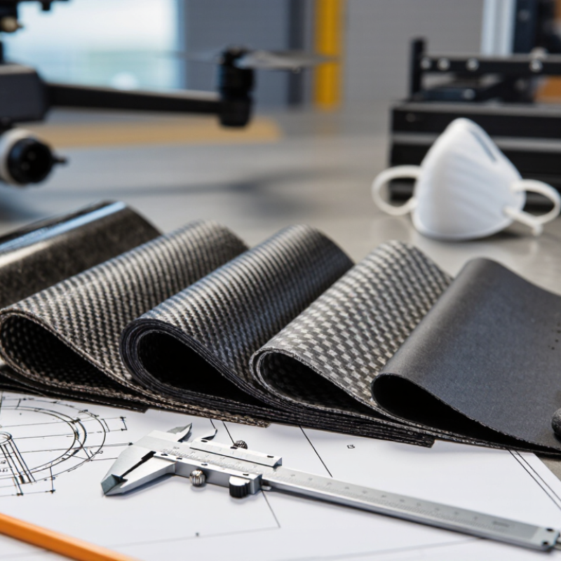
Start with the load, not the appearance. A glossy surface does not prove structural performance. Define tensile, bending, compression, impact, and fatigue requirements before selecting a sheet. According to the U.S. Department of Energy’s Carbon Fiber Technology Facility reports, carbon fiber commonly provides tensile strength near 3,500–5,000 MPa. Its density remains around 1.5–1.6 g/cm³, much lower than steel. These figures describe fiber potential, not finished-sheet performance.
Layup direction matters greatly. A 0-degree layer carries lengthwise tension, while ±45-degree layers improve shear resistance. Cross-ply layers help control widthwise movement. The laminate should also match the expected temperature, moisture, chemicals, and vibration. ASTM D3039 is widely used for tensile testing, while ASTM D790 supports flexural evaluation. Request actual test data, including thickness, fiber orientation, resin system, and test conditions.
Small details can change the result. A two-millimeter edge radius may reduce local stress, while a drilled hole can create a serious weak point. I have seen designers choose a sheet by thickness alone. That shortcut is risky. I also question simplified strength tables because real parts rarely receive perfectly aligned loads. A certificate helps, but independent testing may still be necessary for safety-critical applications.

How to Choose the Right Carbon Fiber Sheet?
Compare Fiber Orientation, Thickness, and Structural Design
Choosing a carbon fiber sheet starts with the load, not the appearance. A glossy surface can hide an unsuitable internal structure. Identify whether the panel mainly carries tension, bending, twisting, or repeated vibration. Then match the fiber orientation to those forces.
Unidirectional fibers provide strong performance along one primary axis. They suit beams, rails, and narrow reinforcement zones. Woven layers offer more balanced strength in two directions. For complex loads, alternating 0°, 90°, and ±45° layers can improve stability. The layup matters greatly. Two sheets with equal thickness may behave very differently.
Thickness is not a simple strength guarantee. A thicker sheet can resist bending better, but it may add weight and create difficult edge transitions. Structural design also includes support spacing, fastener locations, cutouts, and load transfer. A hole near an unsupported edge can cause local cracking. Keep this in mind.
Check the technical data carefully. Look for fiber volume, resin type, void content, tolerance, and test direction. Small gaps or rough edges deserve attention. In a prototype, use a simple load test and inspect damage afterward. It may reveal a poor assumption. I have seen designs fail because engineers measured panel strength but ignored the joint. Reconsider the whole load path, not just the sheet.
| Selection Factor | Typical Option | Fiber Orientation and Behavior | Structural Advantages | Limitations and Design Risks | Recommended Use |
|---|---|---|---|---|---|
| Fiber Orientation | Unidirectional (0°) | Most fibers run in one direction, providing the highest stiffness and tensile strength along the fiber axis. | Efficient for carrying predictable one-directional loads; allows a high fiber volume in the principal load path. | Weakness is more pronounced across the fiber direction; requires careful control of edge loads, splitting, and transverse stresses. | Beams, tension members, reinforcement strips, and parts where the primary load direction is known. |
| Fiber Orientation | Woven 0°/90° | Fibers run in two perpendicular directions, normally producing balanced in-plane properties. | Good handling, dimensional stability, and resistance to loads applied in both principal directions. | The crimp from weaving can reduce straight-fiber efficiency compared with an equivalent unidirectional laminate. | Flat panels, covers, brackets, housings, and components receiving loads in two main directions. |
| Fiber Orientation | Quasi-isotropic laminate [0°/±45°/90°] | Uses multiple orientations to approximate more uniform in-plane behavior. | Supports axial, transverse, and in-plane shear loads more evenly than a single-direction laminate. | Usually heavier and less efficient in one specific direction because some fibers are not aligned with the dominant load. | General-purpose structural panels, complex load paths, vehicle components, and parts with uncertain load direction. |
| Fiber Orientation | ±45° laminate | Fibers are oriented diagonally to carry in-plane shear and torsional loads. | Improves shear transfer, torsional stiffness, and resistance to distortion under angular loading. | Not the most efficient configuration for pure 0° axial tension or compression. | Torsion boxes, drive components, curved shells, and structures exposed to significant in-plane shear. |
| Sheet Thickness | 0.5–1.0 mm | Suitable for thin skins and lightweight covers when bending spans and impact loads are limited. | Low mass and easy trimming; useful where the substrate or a bonded core provides much of the stiffness. | Limited resistance to local buckling, denting, bending, and concentrated fastener loads. | Decorative panels, electronics covers, fairings, instrument panels, and bonded surface skins. |
| Sheet Thickness | 1.5–2.0 mm | Provides a practical balance between bending stiffness, weight, machinability, and surface durability. | Better resistance to panel flexing and local loads than thin sheets without a large thickness penalty. | May still require ribs, edge returns, bonded supports, or a sandwich core for large unsupported spans. | Brackets, access panels, machine guards, lightweight frames, and moderately loaded flat structures. |
| Sheet Thickness | 2.5–4.0 mm | Provides greater laminate depth and improved resistance to bending, compression, and handling damage. | Better suited to structural plates, mounting surfaces, and components with higher local loads. | Higher cost and mass; increasing thickness alone may not solve weak joints, poor load introduction, or buckling between supports. | Structural mounting plates, equipment supports, robot arms, chassis panels, and load-bearing brackets. |
| Structural Design | Flat solid laminate | All laminate material is concentrated in a single solid sheet. | Simple to manufacture, drill, bond, and inspect; useful for compact components. | Can become heavy when high bending stiffness is required over a large unsupported area. | Small to medium parts, rigid covers, brackets, and components with short spans. |
| Structural Design | Sandwich panel with foam or honeycomb core | Thin carbon fiber skins are separated by a lightweight core, increasing the distance between load-carrying faces. | High bending stiffness-to-weight ratio and improved panel stability for larger spans. | Edges, inserts, joints, and concentrated loads need local reinforcement; core damage can reduce performance. | Large panels, aerodynamic surfaces, vehicle floors, enclosures, and lightweight beams. |
| Structural Design | Ribbed or folded sheet | Flanges, ribs, bends, or returns increase the effective section depth without using a solid thick plate. | Improves bending stiffness and resistance to panel buckling while retaining a relatively low mass. | Corners and geometric transitions can create stress concentrations; manufacturing tolerances must be controlled. | Stiff covers, trays, brackets, frames, and panels requiring directional stiffness. |
| Load Introduction | Bonded joint | Loads are transferred through adhesive shear and peel stresses across a bonded overlap. | Distributes load over an area and avoids holes that can reduce net section strength. | Surface preparation, adhesive selection, overlap length, temperature, and moisture resistance are critical. | Clean, lightweight assemblies where bonding processes can be controlled and inspected. |
| Load Introduction | Bolted or mechanically fastened joint | Loads pass through drilled holes, bearing surfaces, fasteners, and local laminate regions. | Removable, inspectable, and suitable where disassembly or field replacement is required. | Hole-edge bearing, net-section tension, pull-through, delamination, and galvanic corrosion must be checked. | Serviceable assemblies, access covers, equipment mounts, and structures requiring removable connections. |
| Design Verification | Basic engineering checks | Evaluate tensile and compressive loads, bending, shear, buckling, deflection, fastener loads, and environmental exposure. | Helps align fiber direction and thickness with actual load paths instead of selecting by appearance alone. | Nominal thickness and advertised strength are not sufficient without laminate schedule, test data, safety factors, and joint details. | All load-bearing applications, especially parts exposed to impact, vibration, heat, fatigue, or human safety requirements. |
How to Choose the Right Carbon Fiber Sheet?
Select the Right Resin System and Surface Finish
Choosing a carbon fiber sheet starts with its resin system, not its appearance. The resin controls temperature resistance, moisture behavior, stiffness retention, and bonding performance. For structural parts, an epoxy system often provides stable mechanical properties and reliable adhesion. Applications exposed to chemicals may require a different formulation. Always check the supplier’s technical data and service temperature.
Think about the real working environment. A panel inside a dry enclosure faces different demands than one near heat, vibration, or cleaning fluids. Cure temperature also matters. A high-temperature resin may perform well, but it can require controlled processing equipment. That is not always practical. Test a small sample when the material will carry significant loads.
Surface finish affects handling, appearance, and installation. A gloss finish highlights weave patterns but shows fingerprints and scratches quickly. A matte finish hides minor marks and reduces glare. A sanded surface can improve bonding, but sanding too deeply may expose fibers. Peel-ply surfaces offer useful texture after removal, although the result can vary with processing quality.
Do not judge strength by shine.
Inspect the sheet for resin-rich edges, waviness, pinholes, and uneven weave. These details may reveal manufacturing variation. Dimensional tolerances deserve attention too, especially for fitted panels. A carefully chosen finish can still disappoint if the sheet thickness is inconsistent. I sometimes prefer a less attractive surface when it bonds more predictably. That trade-off is easy to overlook.
Select the resin system according to temperature and chemical requirements, then choose a surface finish based on bonding, appearance, and dimensional needs.
Lower Ra values generally provide a smoother appearance, while textured finishes can improve mechanical interlocking during secondary bonding.
Values are representative industry ranges and typical midpoints. Actual glass-transition temperature and surface roughness depend on fiber architecture, cure conditions, tooling, and post-processing; always verify the technical datasheet for the selected sheet.
Choosing the right carbon fiber sheet starts with project dimensions, not weave appearance. Measure the finished length, width, thickness, corner radius, and allowable deflection. Add a trim allowance when the cutting process requires it.
CNC routing suits complex profiles and clean internal openings. Waterjet cutting limits heat exposure but still requires edge inspection.
For simple rectangles, saw cutting may reduce cost. Measure twice.
MarketsandMarkets’ 2024 Carbon Fiber Market report estimates growth from about USD 4.3 billion in 2024 to USD 6.3 billion by 2029. More supply does not mean every sheet performs equally. Match the fabrication method to the laminate. A 0°/90° layup supports directional loads, while quasi-isotropic construction handles changing loads with added weight.
That assumption is risky. Check fiber orientation, resin system, surface finish, and thickness tolerance before ordering.
For drilled holes, use carbide tooling, backing support, and effective dust extraction. Delamination often begins at the tool exit.
Bonded parts need controlled abrasion, solvent compatibility, and clean surfaces.
ASTM D3039 tensile testing and ASTM D790 flexural testing provide useful reference data, but small coupons may not represent bolted assemblies. Grand View Research estimates the global carbon fiber market reached approximately USD 4.4 billion in 2023, reflecting strong demand across transportation and energy applications.
Still, a neat-looking sheet can fail after poor edge preparation. Recheck the drawing before fabrication.
Choosing a carbon fiber sheet requires more than checking its thickness or glossy surface. ASTM D3039 data shows that tensile strength can vary widely with fiber direction, resin content, and laminate construction. A 2 mm sheet may perform poorly if its load direction ignores the layup. Ask for batch-specific test results, not only a generic datasheet. Check fiber volume fraction, cure method, thickness tolerance, and void content. ISO 10618 also supports reviewing carbon fiber construction and handling quality.
Compatibility matters under real service conditions. A sheet exposed to heat, moisture, vibration, or chemicals needs supporting evidence from thermal cycling, water absorption, and fatigue testing. The Composite Materials Handbook reports that matrix properties can change significantly near the resin’s glass-transition temperature. Measure the expected temperature range carefully. Then compare it with the supplier’s Tg and recommended operating limit. Too close is risky.
Service life is often underestimated. The 2023 Global Wind Report recorded continued growth in large composite structures, where fatigue performance and inspection access remain practical concerns. Your application may be smaller, but the lesson still applies. Inspect edges for delamination, protect drilled holes, and avoid sharp clamping loads. I would not trust appearance alone. Test a sample under realistic loading, including imperfect installation. That extra step costs time, yet one neglected interface can control the whole structure’s life.
3295 Cobb International Blvd.
Kennesaw, GA 30152
800-367-1377
sale@patiostools.com
© 2023 - Marsh Instruments