3295 Cobb International Blvd. Kennesaw, GA 30152 800-367-1377 sale@patiostools.com

Product Variation:

What Is Differential Pressure and How Does It Work?

Differential pressure describes the difference between pressure at two points, not pressure at one point alone. In a filter housing, for example, a sensor compares pressure before and after the filter. A rising difference may indicate a buildup of trapped dust or liquid. The reading is useful because it turns an invisible change into a number operators can monitor.

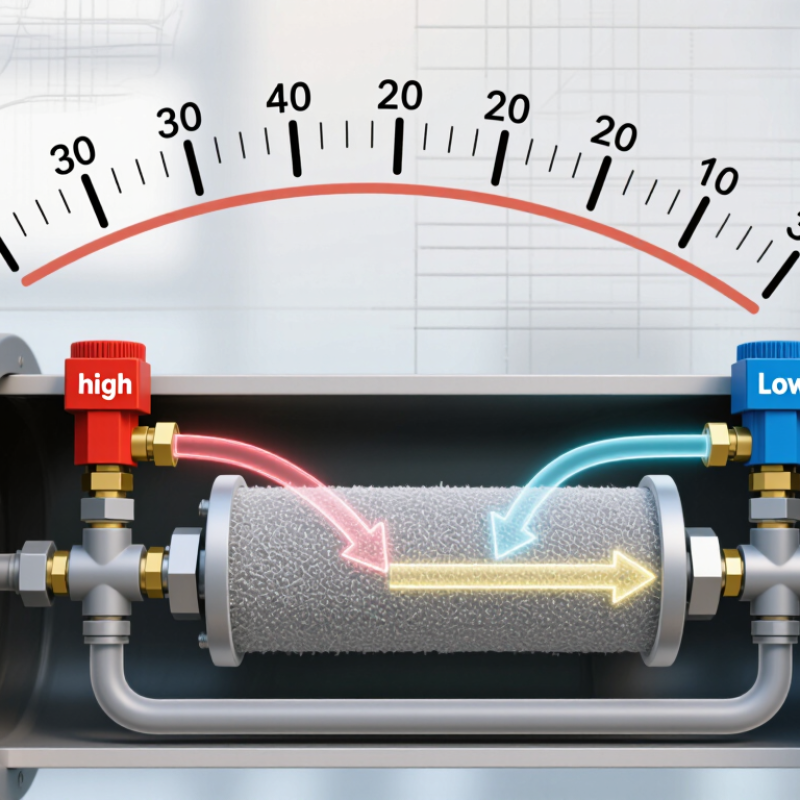
Measurement-science author Richard S. Figliola’s work offers a useful principle, paraphrased here: “A pressure difference is meaningful only when both measurement points and the reference are clear.” That distinction matters. A differential-pressure transmitter uses two pressure connections, often labeled high and low, and converts their difference into a signal. The instrument may display the result in pascals, kilopascals, or inches of water column. Small gaps matter.

The idea sounds simple. Not always. A blocked impulse line, a poor installation, or an incorrect range can distort the reading. Even a reliable sensor cannot correct a bad setup. This guide explains what differential pressure means, how instruments measure it, and where the measurement is used in real systems. It also considers limitations, because a number on a display is not automatically a diagnosis. Knowing what the two ports are sensing is a practical first step toward interpreting that number with care.
What Is Differential Pressure and How Does It Work?

Define Differential Pressure: ΔP = P₁ − P₂, Expressed in Pa

Differential pressure is the difference between two pressures:

ΔP = P₁ − P₂ P₁ is the pressure at one point; P₂ is the pressure at another. The result is expressed in pascals (Pa), where one pascal equals one newton per square metre.

If P₁ is 101,325 Pa and P₂ is 101,322.5 Pa, then ΔP is +2.5 Pa. Very small. A positive value means pressure is higher at point one; a negative value means it is lower.

This measurement matters in ventilation, filtration, and room containment. A differential gauge compares pressure at two ports directly. Technicians can also subtract readings from separate sensors, though mismatched zero points may introduce error. The CDC’s 2003 Environmental Infection Control Guidelines recommend maintaining a negative pressure differential greater than 0.01 inches of water gauge, or 2.5 Pa, in airborne infection isolation rooms. That figure gives a real-world scale for a pressure difference that might otherwise seem abstract.

A 2.5 Pa target is tiny beside atmospheric pressure, so sensor range, placement, and calibration matter. A door opening can briefly change the reading; one snapshot may not tell the whole story. That’s the awkward part: the equation is exact, but real rooms are not steady. Leaking tubing or a blocked pressure tap can quietly mislead an otherwise careful measurement.

Set the SI Scale: 1 Pa = 1 N/m² and 1 bar = 100 kPa

What Is Differential Pressure and How Does It Work?

Differential pressure is the difference between pressure at two points. A sensor compares the pressures through separate ports, then reports their difference. The SI unit is the pascal (Pa). One pascal equals one newton per square metre: 1 Pa = 1 N/m². That relationship connects pressure to force spread across an area. A small pressure change can still matter in a ventilation duct or filter.

The bar is a larger unit. One bar equals 100 kilopascals, or 100,000 pascals: 1 bar = 100 kPa. For example, a reading of 2 kPa is 0.02 bar. The conversion is straightforward, but the reference points matter. A positive reading may mean the first port has higher pressure than the second; reversing the ports can reverse the sign. Check the instrument’s stated convention before interpreting results.

Tips: Keep the units consistent when comparing readings. Check both ports. Note whether the value is differential, gauge, or absolute pressure, since these describe different measurements. A quick conversion can prevent a scale error, though I still find it easy to overlook a misplaced decimal. When recording a result, include the unit and measurement conditions.

Explain Sensors: DP Transmitters Commonly Output a 4–20 mA Signal

A differential-pressure (DP) transmitter compares pressure at two ports. A diaphragm or other sensing element responds to the difference, then electronics convert it into a signal for a control system. The familiar output is 4–20 mA. It is a current signal, so cable voltage drops usually affect it less than they affect voltage-based signals. A small detail matters: the transmitter must be ranged correctly.

At the configured lower pressure limit, the output is typically 4 mA; at the upper limit, it is 20 mA. That gives a 16 mA measurement span. For example, a transmitter ranged from 0 to 100 kPa differential pressure outputs about 12 mA at 50 kPa. IEC 60381-1 specifies direct-current signals used in process-control systems, including the 4–20 mA convention. NAMUR NE 43 defines diagnostic signaling guidance: normal measurement signals generally occupy 3.8–20.5 mA, while currents at or below 3.6 mA, or at or above 21 mA, can indicate a fault. Check the device configuration and receiving system; settings may differ. Real installations are less tidy. Plugged impulse lines, trapped air, or a loose terminal can distort readings, and a plausible current does not prove the pressure taps are clear.

Differential Pressure and 4–20 mA Transmitter Output

A differential pressure transmitter measures the pressure difference between two points and converts it into an electrical signal. For a transmitter calibrated from 0 to 10 kPa, the ideal output increases linearly from 4 mA at 0 kPa to 20 mA at 10 kPa. The 4 mA lower-range value allows the live-zero signal to be distinguished from a zero-current fault.

Show Flow Measurement: ISO 5167 Uses ΔP Across Primary Devices

What Is Differential Pressure and How Does It Work?

In flow measurement, differential pressure is the pressure difference measured across a primary device. ISO 5167 covers devices such as orifice plates, Venturi tubes, and flow nozzles. As fluid passes through a restriction, its velocity rises and static pressure falls. The measured pressure drop helps determine flow rate.

The relationship is useful, but not linear: under specified conditions, flow rate is proportional to the square root of differential pressure. Calculations also depend on factors such as fluid density, device geometry, and discharge coefficient. ISO 5167 sets requirements for device dimensions, pressure tapping, and installation conditions. A poorly positioned tap or insufficient straight pipe can distort readings. Small details count. Real installations can be less tidy than drawings, so verify the setup rather than assuming it matches the standard.

Tips: Check that the device and installation meet the applicable ISO 5167 requirements. Keep impulse lines clear, confirm the pressure transmitter’s zero, and use the correct fluid properties. A noisy or drifting ΔP signal deserves investigation before changing the flow calculation.

What Is Differential Pressure and How Does It Work? — Show Flow Measurement: ISO 5167 Uses ΔP Across Primary Devices

Dimension Technical Detail Why It Matters
Definition of differential pressure Differential pressure (Δp) is the difference between two measured static pressures: Δp = p1 − p2. It indicates the pressure change between an upstream and a downstream measurement point.
How a primary device creates Δp A restriction changes the flow area. Fluid velocity rises through the restriction, while static pressure falls. Downstream, some pressure is recovered as the flow expands. The pressure difference is related to flow rate, so it can be used to infer flow when fluid properties and meter geometry are known.
ISO 5167 flow relationship qv = [C ε A2 / √(1 − β4)] × √(2 Δp / ρ1) For this relation, qv is upstream-condition volume flow, C is the discharge coefficient, ε is the expansibility factor, A2 is the reference area at the restriction, β = d/D, and ρ1 is upstream fluid density.
Square-root behavior For a given meter geometry and fluid condition, flow rate is approximately proportional to √Δp. Doubling Δp therefore does not double flow. A differential-pressure transmitter or flow computer typically applies square-root extraction when converting Δp to flow.
Orifice plate A thin plate with a precisely defined bore creates a restriction. ISO 5167-2 covers orifice plates and their associated pressure-tapping arrangements. It is a widely used differential-pressure primary device; the plate geometry, taps, installation, and operating conditions affect the measurement.
Nozzle and Venturi nozzle A shaped converging profile accelerates the fluid. ISO 5167-3 covers nozzles and Venturi nozzles. The defined profile and pressure-tap arrangement are part of the standardized measurement configuration.
Venturi tube A converging section, throat, and diverging section create a measured pressure difference. ISO 5167-4 covers Venturi tubes. The expanding section allows pressure recovery; permanent pressure loss is generally different from the measured differential pressure.
Cone-type meter A cone-shaped element inside the pipe creates a differential pressure between defined pressure-measurement locations. ISO 5167-5 covers cone-type meters. Its geometry and installation requirements must match the applicable standard and meter specification.
Wedge meter A wedge-shaped element partially restricts the pipe and produces an upstream-to-downstream pressure difference. ISO 5167-6 covers wedge meters. As with other primary devices, flow calculation depends on the specified geometry and valid operating conditions.
Pressure measurement locations Pressure taps connect the pipe at the prescribed upstream and downstream locations to a differential-pressure measurement device. Tap type and location are defined for the applicable primary-device configuration; changing them can change the measured Δp.
Flow calculation inputs Calculation requires Δp, primary-device dimensions, fluid density, and the applicable discharge and expansibility factors. Fluid properties may depend on pressure and temperature. Accurate inputs are necessary to convert a pressure measurement into a reliable flow result.
Installation and operating conditions ISO 5167 specifies conditions for standardized measurement, including device geometry, pressure taps, and upstream and downstream installation requirements. The applicable part sets the relevant limits and details. Flow disturbances, unsuitable geometry, or operation outside the standard’s limits can reduce measurement accuracy.
Measured Δp versus permanent pressure loss Δp is the pressure difference between the selected taps. Permanent pressure loss is the unrecovered pressure decrease after the flow has passed the device. These are not interchangeable quantities; a portion of the pressure difference can be recovered downstream.

Important: ISO 5167 calculations apply only when the primary device, fluid, flow conditions, and installation meet the requirements of the relevant part of the standard. Consult the applicable edition for detailed limits and procedures.

Compare Applications: HVAC, Filtration, and Cleanrooms Monitor ΔP

Differential pressure (ΔP) is the difference in air pressure between two points. In HVAC systems, sensors often compare pressure before and after a filter or across a room boundary. As a filter collects dust, resistance usually rises and the pressure drop may increase. That matters. A rising reading can signal a need to inspect the filter, but it does not prove the filter is the only cause. Fan speed, airflow, and blocked sensing tubes can also affect the result.

Filtration systems use ΔP to track how much resistance a filter creates during operation. Technicians may compare readings with the system’s specified operating range and check that airflow remains adequate. A single number can mislead. Readings are more useful when recorded over time, under similar operating conditions, and alongside airflow checks. Even careful measurements are snapshots, not a complete picture of filter performance.

In cleanrooms, pressure differences help maintain airflow from cleaner areas toward less clean spaces. For example, a controlled pressure cascade can reduce the chance that air moves from a corridor into a cleaner room when a door opens. Small details matter: door position, occupied conditions, and sensor placement can shift readings. Staff should verify alarms and calibration rather than treating a displayed value as unquestionable. The room may meet its pressure target while airflow patterns still deserve a closer look.