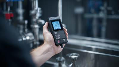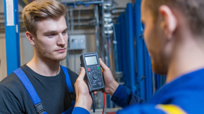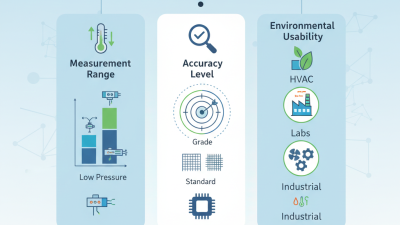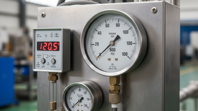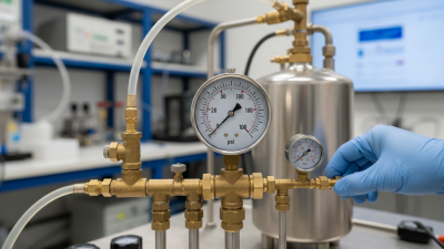
A digital manometer is a precision instrument that measures pressure and presents the reading on an electronic display. It can measure gauge, absolute, or differential pressure, depending on its sensor and configuration. Unlike a traditional liquid-column manometer, it does not require a technician to read a changing fluid level. The value appears in pascals, kilopascals, bar, psi, or other selected units.
Its operation is compact but not simplistic. Pressure acts on a sensing element, often a piezoresistive or MEMS sensor. That mechanical response becomes an electrical signal. An analog-to-digital converter then processes the signal. The instrument applies calibration data, temperature compensation, and sometimes filtering. Finally, the display shows a stable measurement. Some models also record minimum and maximum values, export data, or trigger alarms.
Small errors still matter. A low battery, blocked port, vibration, or poor zeroing can change the result. NIST Special Publication 811 supports consistent SI-unit use, while IEC 61298-2 describes methods for evaluating process-measurement performance. ISO/IEC 17025 also emphasizes competent calibration laboratories and traceable results. These references help explain why a digital manometer should not be judged by screen resolution alone. Accuracy, repeatability, response time, drift, and calibration records are equally important.
Industry market reports often forecast continued growth in digital pressure instrumentation, driven by HVAC maintenance, process control, laboratory testing, and energy management. However, reported market values differ by research method and product definition. That inconsistency deserves caution. A practical evaluation should begin with the pressure range, media compatibility, required uncertainty, and working environment. Then, the instrument’s specifications can be compared with a calibrated reference. That is where theory meets the technician’s hand.
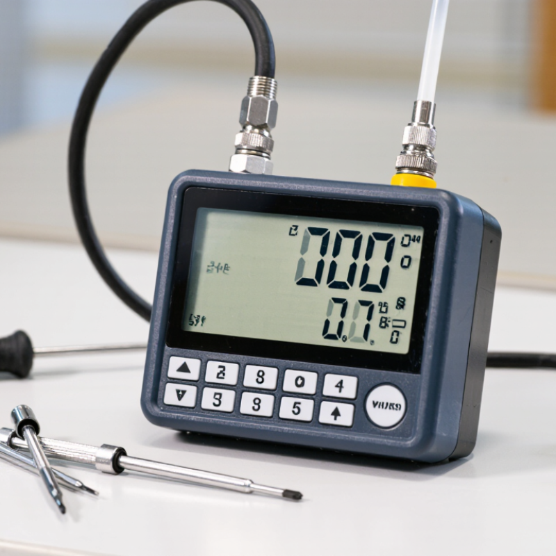
A digital manometer is an electronic instrument that measures pressure and displays the result on a screen. Its core purpose is simple: make pressure differences visible, readable, and easier to record. Unlike a liquid-column manometer, it uses a pressure sensor instead of a moving column of fluid. The sensor detects force from air, gas, or another compatible medium. Internal circuits convert that force into a digital value. The display may show pascals, kilopascals, bar, inches of water column, or other selected units. Clear units matter. A correct number can still cause confusion if the unit is wrong.
In practical work, technicians connect the instrument to a pressure point, zero it, and compare the reading with a target range. A differential model measures the difference between two ports. A gauge model compares pressure with surrounding atmospheric pressure. An absolute model uses a sealed vacuum reference. These distinctions determine what the reading actually means. Good measurement also requires sound tubing, stable connections, and regular calibration checks. I have seen a steady display create false confidence when a hose leaked near the fitting. Digital does not mean infallible. Temperature, overpressure, sensor drift, and poor setup can affect accuracy. The instrument supports a decision; it does not replace careful judgment. That point deserves more attention.
A digital manometer measures pressure and converts it into a readable electronic value. Its sensing element usually contains a flexible diaphragm. Pressure bends this diaphragm slightly. A piezoresistive or capacitive sensor detects the movement and produces an electrical signal.
The signal-conditioning circuit filters small electrical changes and reduces noise. An analog-to-digital converter then changes the signal into numerical data. A microprocessor applies pressure calculations, temperature compensation, and selected unit conversions. The display presents values in units such as pascals, kilopascals, or inches of water. Clear digits matter in dim plant rooms.
Pressure ports connect the instrument to tubing or test points. A differential model uses two ports and compares high pressure with low pressure. A gauge model compares pressure with surrounding air. An absolute model uses a sealed vacuum reference. Seals help prevent leakage, while the housing protects internal parts from dust and accidental impacts. Batteries provide portable power, though weak batteries can create unstable readings.
Technicians should zero the instrument before testing. They should also inspect tubing for cracks and blocked openings. Field checks often reveal a simple problem: the display works, but the connection leaks. Calibration against a trusted reference improves confidence. Still, temperature changes, vibration, and overpressure can affect accuracy. A clean number is not automatically a correct measurement.
A digital manometer measures pressure by converting force into an electrical signal. Pressure pushes against a thin diaphragm inside the sensor. The diaphragm moves slightly. A strain-gauge or capacitive element detects that movement and changes it into a voltage. An analog-to-digital converter then transforms the signal into a readable pressure value.
The instrument compares pressure with a reference. Gauge models compare it with surrounding atmospheric pressure. Differential models compare two connected pressure points. Absolute models use a sealed vacuum reference. Temperature compensation matters because sensor materials expand and contract. The display may show pascals, bar, psi, or inches of water column. Small errors remain possible. A blocked tube, weak battery, or poor zeroing can distort the reading.
According to the U.S. Department of Energy’s Improving Compressed Air System Performance guide, compressed air can consume about 10% of industrial electricity. Reliable pressure checks can reveal leaks, clogged filters, and excessive pressure settings. A 2024 Fortune Business Insights report estimated the global pressure sensor market at roughly 14 billion U.S. dollars in 2023, showing the growing role of electronic measurement. These figures describe a broad sensor industry, not digital manometers alone.
In field testing, technicians often zero the instrument before connecting it. They also compare readings with a calibrated reference. That habit is more important than a bright display. NIST Technical Note 1297 emphasizes reporting measurement uncertainty, yet many quick inspections record only the displayed number. That is a weakness worth admitting. A pressure value without units, reference type, and calibration status is incomplete.
A digital manometer measures pressure with a sensor and displays the result on a screen. Inside, a pressure-sensitive element changes slightly when air or liquid pushes against it. Electronics convert that change into a readable value. A technician can then compare the reading with a system’s expected range. It feels simple, but sensor drift and poor zeroing can affect accuracy.
Pressure has several useful forms. Gauge pressure compares system pressure with surrounding atmospheric pressure. Absolute pressure compares it with a near-perfect vacuum. Differential pressure shows the difference between two connection points, such as both sides of a filter. Vacuum readings describe pressure below atmospheric pressure. Common units include pascals (Pa), kilopascals (kPa), bar, pounds per square inch (psi), inches of mercury (inHg), and millimeters of mercury (mmHg). One unit is not automatically better. The correct choice depends on the equipment, application, and required resolution. Mixing units can create a surprisingly serious mistake.
Tips: Check the selected unit before recording a value. Zero the instrument in stable conditions. Keep both pressure ports clean and dry. Let the sensor adjust to temperature changes. When a reading looks unusual, measure again and inspect the connections. I have found that rushing this check often causes more confusion than the pressure problem itself. Calibration records also help, although they do not replace careful handling.
A digital manometer measures pressure by sensing force across a diaphragm and converting it into an electrical signal. The display then shows gauge, absolute, or differential pressure. In field inspections, technicians use it to check filters, ventilation ducts, gas lines, pumps, and pneumatic tools. Differential models are especially useful when a clogged filter creates a small pressure drop. The U.S. Department of Energy reports that compressed-air systems can consume 10% to 30% of industrial electricity, so accurate pressure checks may reveal costly leaks or excessive operating pressure.
Its main benefits are clear readings, compact size, easy data logging, and rapid unit conversion. Some models also record minimum and maximum values, helping technicians capture pressure spikes that a mechanical gauge may miss. However, a digital display does not guarantee reliable measurement. NIST Technical Note 1297 explains that reported uncertainty should include calibration, resolution, repeatability, and environmental effects. Temperature, vibration, condensation, and a blocked impulse tube can distort the result. A reading may look precise but still be wrong. Pressure pulsation is another concern. Averaging can stabilize the screen, yet it may hide dangerous peaks. Calibration should follow the instrument’s risk level and the requirements of an ISO/IEC 17025-accredited laboratory when traceability matters. Field users sometimes trust the last calibration date too much; sensor aging and damaged seals deserve equal attention. A practical limitation remains: the manometer measures pressure, not the root cause of a system fault.
| Data Dimension | Description | Typical Data or Example | Measurement Considerations |
|---|---|---|---|
| Definition | A digital manometer is an electronic instrument that measures pressure and displays the result numerically on a screen. | Common measurements include gauge, differential, absolute, and vacuum pressure. | The instrument must be selected for the correct pressure type and operating range. |
| Basic Working Principle | Pressure acts on a sensing element, causing a measurable change in an electrical property. Internal electronics convert this signal into a pressure reading. | MEMS piezoresistive sensors are widely used for low- and medium-pressure measurement. | Sensor output can be affected by temperature, vibration, electrical noise, and mechanical shock. |
| Pressure Types | Gauge pressure is measured relative to atmospheric pressure; absolute pressure is measured relative to a vacuum reference; differential pressure is the difference between two ports. | Differential pressure: ΔP = P1 − P2. | A gauge reading can change with atmospheric pressure, while absolute and differential instruments use different reference arrangements. |
| Common Units | Digital manometers may support multiple pressure units to match engineering, laboratory, HVAC, or industrial requirements. | Pa, kPa, MPa, bar, mbar, psi, inH₂O, mmH₂O, inHg, and mmHg. | Unit conversions and the selected reference pressure should be checked before recording or comparing results. |
| Typical Measuring Ranges | Available ranges vary substantially by sensor design and intended application. | Low differential pressure: tens to thousands of pascals; general gauge pressure: approximately 0.1 to 10 bar; specialized instruments may cover higher pressures. | Operating near the upper limit may reduce accuracy or overload the sensor. The specified range should not be exceeded. |
| Resolution | Resolution is the smallest displayed increment or detectable pressure change. | Typical displays may provide 0.1 Pa, 1 Pa, 0.01 kPa, or 0.1 psi resolution, depending on range and design. | High displayed resolution does not necessarily mean high accuracy or repeatability. |
| Accuracy | Accuracy describes how close the indicated value is to the reference pressure under specified conditions. | Portable instruments commonly specify accuracy as a percentage of full scale or reading, such as ±0.25% of full scale. | Accuracy may change with temperature, calibration status, pressure direction, range selection, and time. |
| Response and Sampling | Response time is the time required for the display or output to follow a pressure change. Sampling rate determines how frequently the sensor is read. | A stable display may require digital averaging, while fast sampling is useful for observing transient pressure changes. | Averaging improves stability but can hide short-duration peaks or rapid fluctuations. |
| HVAC and Airflow Testing | Differential digital manometers are used to check filter pressure drop, duct pressure, fan performance, and combustion-air systems. | Low-pressure measurements are commonly expressed in Pa, kPa, or inH₂O. | Incorrect hose connections, leaks, airflow pulsation, and poor zeroing can produce misleading results. |
| Industrial Process Monitoring | Digital manometers can verify pressure in pneumatic systems, process lines, regulators, pumps, and test equipment. | Gauge or differential pressure may be monitored during commissioning, maintenance, and troubleshooting. | The wetted materials must be compatible with the process fluid, pressure, temperature, and contamination level. |
| Laboratory and Calibration Use | High-resolution manometers can be used for comparative tests, pressure source checks, and calibration procedures. | Measurements are compared with a traceable reference under controlled environmental conditions. | A digital manometer is not automatically a calibration standard; traceability depends on documented calibration and uncertainty. |
| Key Benefits | Digital instruments offer clear numerical readings, selectable units, data-hold functions, compact construction, and reduced reading-parallax error compared with analog scales. | Many models also provide auto-zero, minimum/maximum capture, backlighting, or data logging. | Electronic features depend on battery power, firmware, sensor stability, and correct configuration. |
| Temperature Effects | Changes in ambient or media temperature can alter sensor characteristics, reference pressure, and materials. | Accuracy specifications are often stated at a defined reference temperature, such as 20–25 °C. | Measurements outside the specified temperature range may require compensation or additional uncertainty analysis. |
| Overpressure Protection | Overpressure protection limits damage when the applied pressure temporarily exceeds the measurement range. | Protection levels vary by design and may be specified as a percentage or multiple of full-scale pressure. | Repeated or severe overpressure can cause permanent zero shift even when no visible damage occurs. |
| Calibration and Maintenance | Periodic calibration compares the instrument with a known reference and adjusts or documents its performance. | Calibration intervals are commonly set by usage, risk, environmental conditions, and required measurement uncertainty. | Zero checks do not replace full calibration. Blocked ports, damaged hoses, moisture, and contaminated sensors require attention. |
| Main Measurement Limitations | Digital manometers can be limited by sensor drift, range selection, temperature sensitivity, response lag, fluid compatibility, and insufficient reference stability. | The total measurement result may include sensor accuracy, resolution, repeatability, environmental effects, and reference uncertainty. | For critical work, the complete measurement uncertainty and installation conditions should be evaluated rather than relying only on the display value. |
Note: Typical values are representative engineering ranges rather than universal specifications. Always verify the instrument’s datasheet, calibration status, pressure reference, media compatibility, and safe operating limits before use.
3295 Cobb International Blvd.
Kennesaw, GA 30152
800-367-1377
sale@patiostools.com
© 2023 - Marsh Instruments