What Is an Industrial Digital Camera and How Does It Work?
An Industrial Digital Camera is more than a high-resolution device mounted above a production line. It is a sensing tool designed for controlled, repeatable inspection. Unlike a consumer camera, it often provides global-shutter capture, precise triggering, industrial connectors, and stable operation in heat, dust, or vibration. Its purpose is simple: capture reliable images that software can measure.
Jeff Bier, founder of the Embedded Vision Alliance, describes the wider concept clearly: “Embedded vision is the use of computer vision in embedded systems.” An Industrial Digital Camera applies that idea to manufacturing. A light source illuminates a metal surface. The lens focuses its edges. A sensor converts incoming photons into electrical signals. The camera then sends digital pixel data to a computer, PLC, or vision controller. That system may check labels, detect cracks, measure gaps, or guide a robotic arm.
The process sounds straightforward. It is not always.
Image quality depends on exposure, lens selection, lighting geometry, sensor size, and timing. A camera with more megapixels may still produce poor results if reflections hide a defect. I have seen inspection concepts fail because engineers selected resolution before studying the object’s surface. That mistake is easy to repeat. A better design begins with the defect, not the camera brochure.
This article explains how an Industrial Digital Camera works, which components shape its performance, and where industrial imaging decisions become difficult. It also considers practical limitations, because reliable vision is built through testing, adjustment, and occasional reconsideration.
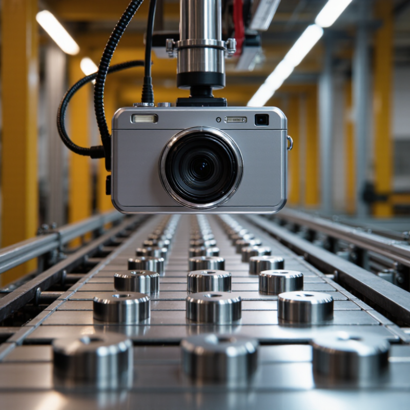
Industrial Digital Cameras: Definition, Role, and Machine-Vision Applications
An industrial digital camera is a rugged imaging device built for automated inspection, measurement, and process control. Unlike a general-purpose camera, it prioritizes repeatable image capture over visual appeal. A sensor converts reflected light into digital data, while a lens controls focus, field of view, and image scale. A trigger may capture each product as it passes beneath the camera.
Its role in machine vision is practical and specific. The camera supplies images, but software interprets them against defined rules or trained models. In a packaging line, it can check labels, cap placement, print quality, and surface damage. In electronics manufacturing, it may locate components or measure alignment within tight tolerances. Fast exposure times can freeze a moving object, while controlled lighting reveals scratches that ordinary room light hides. Stable mounting matters too.
In real installations, reliability depends on more than resolution. Dust, vibration, glare, and changing illumination can weaken results. A high-pixel camera may still produce poor data if the lens is unsuitable or the lighting is inconsistent. That mistake is common. Calibration, trigger timing, and regular verification deserve equal attention. Operators should also define acceptable variation before deployment, because machine vision cannot repair unclear quality standards. It is powerful, but not automatically intelligent.
CMOS Sensors: Pixel Size, Global Shutter, and 8–16-Bit Image Capture
An industrial digital camera converts light into measurable image data for inspection, robotics, and laboratory systems. At its core, a CMOS sensor contains millions of pixels. Each pixel collects photons, then converts them into an electrical signal. Pixel size matters. Larger pixels usually gather more light and produce cleaner images in dim conditions. Smaller pixels can reveal finer details, but they may increase noise and demand better optics.
Global shutter captures all pixels at nearly the same moment. This helps preserve the shape of a fast conveyor belt part or rotating component. A rolling shutter reads different image rows at different times, which can create skewed edges. Image depth also affects measurement quality. An 8-bit image provides 256 tonal levels per channel, while 12-, 14-, or 16-bit capture records subtler brightness changes. More bits do not automatically create better images. Lighting, lens quality, sensor noise, and software settings remain critical.
Tips: Match pixel size to the smallest feature you need to inspect. Choose global shutter for moving targets. Use higher bit depth when shadows and highlights must remain visible. Test the camera with real materials, not only a printed chart. In practice, specifications can look impressive but perform poorly under factory lighting. That part is easy to overlook. Recheck exposure, gain, and lens focus after installation, because small changes can affect repeatability.
Camera Interfaces: GigE Vision, USB3 Vision, and 10GbE Bandwidth
What Is an Industrial Digital Camera and How Does It Work?
An industrial digital camera converts light into measurable image data for inspection, measurement, and automation. Its sensor captures each frame, while internal electronics prepare the pixels for transfer. The interface then carries this data to a computer or controller. In practical testing, cable quality, software settings, and processing speed matter as much as sensor resolution.
GigE Vision uses standard Ethernet infrastructure and supports long cable runs, often useful across large production cells. USB3 Vision can deliver strong throughput through a direct connection, but cable length and host-controller stability need attention. 10GbE provides substantially more bandwidth for high-resolution sensors and fast frame rates. More bandwidth helps, but it does not automatically remove latency or dropped frames. Storage speed, network design, and CPU load remain important. I have seen systems fail because engineers measured only peak interface speed. That was an incomplete assumption.
Tips: Match the interface to distance, frame size, and required frame rate. Test the complete path, including cables, connectors, drivers, and storage. Leave practical bandwidth headroom. A camera may operate perfectly in a short bench test, then lose frames near a busy network. Check packet delays, exposure timing, and trigger signals under real production conditions. Small details matter. Also, document the settings that worked. Without records, troubleshooting becomes guesswork, and even experienced teams can repeat the same mistake.
Industrial Digital Camera Interfaces and Bandwidth
GigE Vision commonly uses a 1 Gb/s Ethernet link, USB3 Vision operates over USB 3.x links up to 5 Gb/s for standard USB 3.0 implementations, and 10GigE Vision provides a nominal 10 Gb/s link. These are theoretical interface rates; image payload, protocol overhead, cable length, host performance, and camera settings affect actual throughput.
Industrial Reliability: IP65–IP67 Protection, Calibration, and Accuracy Control
An industrial digital camera captures light and converts it into measurable image data. It usually works with a lens, sensor, processor, and communication interface. In production environments, the image may guide inspection, measurement, or machine control. A sharp picture is not enough. The camera must remain stable around vibration, dust, moisture, and changing temperatures.
Dust is unforgiving. IP65 protection keeps dust out and resists water jets. IP66 adds stronger water-jet protection, while IP67 supports temporary immersion under defined conditions. These ratings describe enclosure protection, not complete system reliability. Cable glands, connectors, lens covers, and installation angles also matter. A poorly sealed connection can defeat a well-rated housing. This detail is often missed during field installation.
Calibration turns captured pixels into dependable measurements. Technicians may use certified reference targets, uniform lighting, and fixed camera distances. They check brightness response, lens distortion, focus, and dimensional accuracy. Temperature should be recorded because sensors and mechanical mounts can shift slightly. Repeat measurements reveal drift better than one successful test. Small errors matter. A camera may produce attractive images while reporting incorrect dimensions. It is easy to trust a clean image too quickly. Regular verification, documented tolerances, and controlled cleaning routines create stronger accuracy control. Yet calibration is not permanent; vibration, lens replacement, and lighting changes can require another inspection.