
3295 Cobb International Blvd. Kennesaw, GA 30152 800-367-1377 sale@patiostools.com

Product Variation:

What Is a Mini Circuit Breaker and How Does It Work?

A Mini Circuit Breaker is a compact protection device found inside homes, offices, factories, and control panels. It interrupts abnormal current before overheated wiring causes damage. The device usually combines two mechanisms: a thermal bimetal strip for overloads and an electromagnetic trip for short circuits. Its small DIN-rail body can protect a lighting circuit, socket outlet, or motor branch.

The International Energy Agency’s Electricity 2024 report expects global electricity demand to keep rising through 2026, increasing pressure on reliable distribution equipment. Meanwhile, Grand View Research reports continued growth in the global circuit breaker market, supported by construction, industrial automation, and grid modernization. These figures do not describe every Mini Circuit Breaker directly. That distinction matters. Market numbers can look more precise than they really are.

Mike Holt, a widely cited electrical educator, explains the core purpose clearly: “Circuit breakers are designed to protect the conductors.” This principle guides practical selection. Installers must check rated current, voltage, pole configuration, tripping curve, and breaking capacity. A residential B-curve device may respond differently from a C-curve model used with equipment having higher starting current. IEC 60898-1 provides an important reference for low-voltage circuit breakers in household and similar applications.

The front label is small. The consequences are not. A poorly matched breaker may trip too often, or fail to provide suitable protection. That is an uncomfortable point. A Mini Circuit Breaker is not a universal safety solution; correct cable sizing, installation quality, testing, and maintenance remain essential.
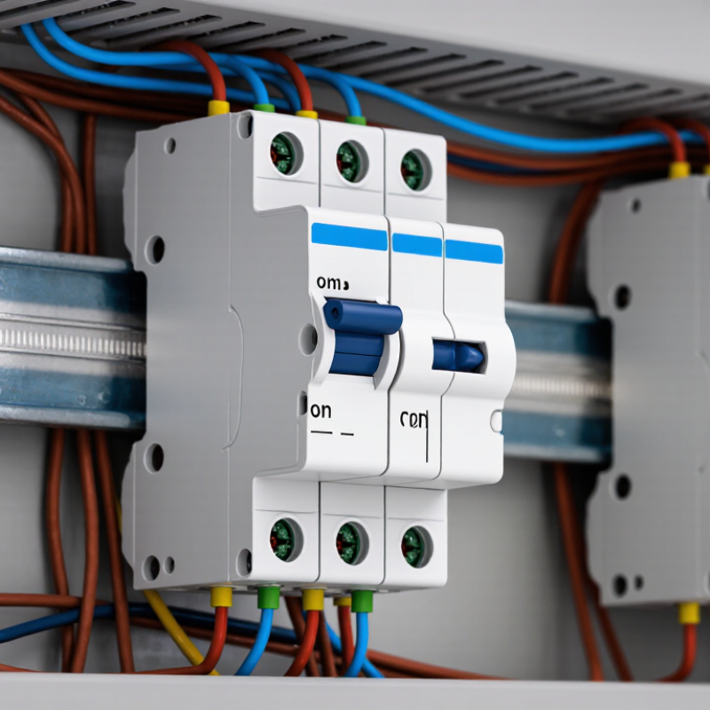
What Is a Mini Circuit Breaker and How Does It Work?

Definition and Core Purpose of a Miniature Circuit Breaker

A miniature circuit breaker, or MCB, is a resettable protective switch for low-voltage electrical circuits. Its core purpose is simple: interrupt dangerous overcurrent before wires overheat. IEC 60898-1 covers MCBs for household and similar applications, including systems up to 440 volts AC and ratings up to 125 amperes.

The device typically uses two release mechanisms. A thermal element responds to sustained overloads, while a magnetic element trips rapidly during a short circuit.

That distinction matters. A kettle may create an overload; damaged insulation may create a short circuit.

The MCB opens its contacts and isolates the affected circuit. After the fault is corrected, the lever can usually be reset. It is not a surge protector. Selection still requires careful attention to rated current, tripping curve, number of poles, and breaking capacity.

The International Energy Agency’s Electricity 2024 report recorded 2.2% global electricity-demand growth in 2023 and projects average annual growth of 3.4% through 2026. More connected loads make correct protection increasingly important.

NFPA’s Home Fires Involving Electrical Distribution and Lighting Equipment report found about 32,000 related home fires annually in the United States from 2016 to 2020. These figures do not mean an MCB prevents every fire. Installation quality remains critical.

A larger rating is not automatically safer. That is where mistakes happen. An underrated circuit trips unnecessarily; an overrated one may let wiring heat for too long.


Main Components and Internal Construction

A mini circuit breaker is a compact protective switch fitted inside a distribution board. Its molded insulating housing separates live parts from the surrounding enclosure. Inside, copper terminals connect the incoming and outgoing conductors. The moving contact meets a fixed contact during normal operation. A spring-loaded toggle moves these contacts manually. It also resets the breaker after a trip. It stays compact.

The protection system uses two main release elements. A bimetal strip bends when continuous overload current produces heat. This slow movement releases the trip latch. A magnetic coil reacts much faster to a severe short circuit. Its plunger pushes the same latch mechanism, opening the contacts rapidly. When the contacts separate, an arc forms. Metal plates in the arc chamber divide, cool, and extinguish it. The design looks simple, but timing is critical. A weak spring, worn contact, or loose terminal can change performance. That detail matters.

During inspection, technicians often look for heat discoloration near the terminals. They also check whether the toggle feels firm and resets correctly. Internal parts should not be opened casually, because insulation spacing and calibrated mechanisms can be disturbed. Circuit ratings must match the conductor size and expected load. The compact body hides a carefully coordinated structure, not merely a switch. My explanation may simplify some construction variations, since manufacturers use different contact shapes and arc-chamber layouts.

What Is a Mini Circuit Breaker and How Does It Work? - Main Components and Internal Construction

Category Main Component or Characteristic Typical Material or Specification Function in the Mini Circuit Breaker Operating Principle or Technical Detail
Definition Miniature circuit breaker Low-voltage, resettable protective switching device Protects electrical circuits against overloads and short circuits. Automatically opens the circuit when the current exceeds the permitted operating condition and can be reset after the fault is cleared.
Typical application Final circuits in residential, commercial, and light industrial installations Distribution boards and consumer units Provides overcurrent protection for lighting, socket, control, and small power circuits. Usually installed on the line conductor; the protected circuit is connected through the device terminals.
Housing Insulating enclosure Molded thermoplastic with flame-resistant properties Insulates live parts and protects the internal mechanism from dust, accidental contact, and mechanical damage. The enclosure is designed to withstand normal operating temperatures and contain the effects of an internal arc.
Current path Fixed and moving contacts Conductive metal contact assemblies Carries the normal load current when the breaker is closed. The contacts separate when the thermal or magnetic trip mechanism operates, interrupting current flow.
Overload protection Thermal bimetal strip Two bonded metals with different thermal expansion rates Detects sustained overcurrent conditions that may overheat conductors. Excess current heats and bends the bimetal. After a time delay, it releases the trip mechanism. The greater the overload, the faster the response.
Short-circuit protection Magnetic trip unit Electromagnetic coil, plunger, or armature Responds rapidly to very high fault currents. The magnetic field produced by the fault current moves the plunger or armature and releases the trip latch, typically within a fraction of a second.
Trip mechanism Latch and spring-operated mechanism Mechanical latch, toggle, springs, and links Separates the contacts and maintains a reliable open position after a fault. The mechanism is generally designed to trip freely, meaning a fault can open the contacts even if the operating handle is held in the closed position.
Operating handle Manual toggle or actuator Insulated polymer handle connected to the internal mechanism Allows manual switching, resetting, and visual indication of the breaker position. Common positions include ON, OFF, and a tripped position. A trip reset normally requires moving the handle fully to OFF before returning it to ON.
Arc control Arc chute and splitter plates Stacked metal de-ionizing plates Reduces and cools the electrical arc created when the contacts open under load. The arc is divided into smaller arcs and moved into the chute, where it is lengthened, cooled, and extinguished.
Terminal system Line and load terminals Screw-clamp terminals with conductive alloy clamps Connects the breaker securely to incoming supply and outgoing circuit conductors. Terminal capacity depends on the device design. Conductors must be correctly sized, fully inserted, and tightened to the specified torque.
Busbar connection Plug-on or comb-busbar interface Conductive terminal clip or compatible busbar connection Distributes supply power to multiple breakers in a structured distribution board. The connection reduces wiring complexity but must match the breaker configuration and the distribution-board system.
Rated current Continuous current rating Common domestic ranges include approximately 2 A to 63 A Indicates the current the breaker is designed to carry continuously under specified reference conditions. The selected rating must coordinate with the conductor ampacity and the expected circuit load. Actual available ratings vary by design and standard.
Rated voltage System voltage rating Common low-voltage systems include approximately 120 V, 230 V, or 400 V AC configurations Defines the maximum system voltage for which the breaker is intended to provide safe switching and protection. The device must be suitable for the supply voltage, frequency, pole arrangement, and installation environment.
Breaking capacity Short-circuit interruption rating Frequently specified in the range of 3 kA to 10 kA for common installations Indicates the maximum prospective fault current the breaker can interrupt safely at its rated voltage. The selected breaking capacity must be equal to or greater than the prospective short-circuit current at the installation point.
Trip characteristic Instantaneous magnetic trip curve Common curves include B, C, and D Defines the approximate instantaneous-trip response range for high fault currents. B-type devices generally trip at about 3–5 times rated current, C-type at about 5–10 times, and D-type at about 10–20 times, subject to the applicable standard.
Pole arrangement Single-pole, double-pole, or multi-pole construction One protected pole per phase or circuit path, depending on design Controls and protects one or more conductors in the circuit. Multi-pole devices use a common or linked operating mechanism so that the associated poles operate together when required.
Reset capability Reusable switching mechanism Manual reset after automatic tripping Restores the circuit after the fault has been identified and corrected. Unlike a fuse, the breaker normally does not require replacement after a standard overload or short-circuit trip.
Safety limitation Overcurrent protection only Does not normally provide residual-current or earth-leakage protection Protects conductors and equipment from excessive current, but not necessarily people from electric shock. Additional residual-current protection may be required where regulations, installation conditions, or the circuit application demand it.
Note: Ratings and construction details are representative of commonly used low-voltage miniature circuit breakers. Exact values, terminal arrangements, dimensions, and trip curves depend on the applicable electrical standard and the specific device design.

How a Miniature Circuit Breaker Detects Faults

What Is a Mini Circuit Breaker and How Does It Work?

A miniature circuit breaker detects abnormal current and disconnects a circuit automatically. It protects cables from overheating, fire, and damage. According to the NFPA Home Structure Fires report, electrical distribution and lighting equipment appeared in about 24% of reported home fires from 2016–2020. That figure gives the device a serious job. However, an MCB does not detect every electrical hazard. It mainly responds to excessive current.

Inside the breaker, a bimetal strip detects prolonged overloads. Rising current heats the strip, causing it to bend and release the switching mechanism. The response is slow enough to tolerate normal startup currents. A magnetic coil reacts much faster to severe short circuits. Its strong electromagnetic force trips the contacts within a very short time. The IEC 60898-1 standard defines key requirements for low-voltage circuit breakers used in household and similar installations. Trip curves still matter. A motor circuit and a lighting circuit may need different responses.

When the contacts separate, an internal arc can form. Arc chutes divide and cool that arc before it becomes dangerous. The handle may move to a middle position, showing that a fault occurred. I have seen people reset a tripped breaker repeatedly. That is not a diagnosis. Heat, loose terminals, damaged insulation, or an oversized load may remain hidden. A qualified electrician should inspect the circuit before restoring power. The mechanism is reliable, but the installation around it is not always tidy.

Step-by-Step Operation During Overload and Short Circuit

What Is a Mini Circuit Breaker and How Does It Work?

A mini circuit breaker protects a low-voltage circuit from excessive current. During practical panel checks, the operating sequence is easier to understand by separating overloads from short circuits.

An overload develops gradually An overload develops gradually, perhaps when too many heaters share one circuit. The current heats a bimetal strip inside the breaker. As the strip bends, it releases the trip latch. The contacts then separate, stopping current flow. The small arc between them is directed into an arc chamber and divided into safer, shorter segments.

A short circuit behaves differently. A short circuit behaves differently. It may occur when live and neutral conductors touch because of damaged insulation or a loose connection. The current rises almost instantly. A magnetic coil senses this sharp increase and pulls the trip mechanism without waiting for thermal heating. The contacts open in a fraction of a second. Fast action limits conductor damage, but it cannot repair the original fault. A common mistake is resetting the breaker repeatedly. That habit needs reconsideration. The circuit should be inspected before power is restored.

Tips: Switch off connected loads before testing the circuit. Check for heat, discoloration, loose terminals, and damaged insulation. Never increase the breaker rating to stop nuisance tripping. The cable must safely carry the protected current. If the cause remains unclear, a qualified electrician should test the installation with suitable instruments.

Types, Ratings, and Common Applications of MCBs

What Is a Mini Circuit Breaker and How Does It Work?

A mini circuit breaker, or MCB, protects low-voltage circuits from overloads and short circuits. Inside, a thermal element responds to prolonged excess current, while a magnetic trip reacts almost instantly to severe faults. The handle then moves to the off position. That small click matters. Unlike a fuse, an MCB can usually be reset after the fault is removed. However, resetting without finding the cause is unsafe and often overlooked.

MCBs are commonly identified by trip curves, pole arrangements, rated current, and breaking capacity. Type B curves suit lighting and general household circuits because they trip at relatively low surge levels. Type C curves tolerate higher starting currents from pumps, tools, and small motors. Type D curves handle larger inrush currents, but require careful engineering. Ratings such as 6 A, 16 A, or 32 A must match the cable size and expected load. The breaking capacity, measured in kiloamps, must also exceed the prospective fault current. More capacity is not automatically better.

Common applications include lighting boards, socket circuits, control panels, and compact commercial equipment. Single-pole units protect one live conductor, while two-pole or multi-pole versions disconnect linked conductors together. In practice, selection depends on installation conditions, ambient temperature, conductor length, and local electrical standards. The correct choice is not always obvious. A qualified electrician should verify calculations, connections, and test results before energizing the circuit.

MCB Magnetic Trip Curves and Typical Applications

Miniature circuit breakers (MCBs) combine thermal overload protection with magnetic short-circuit protection. Under IEC 60898-1 trip characteristics, the instantaneous magnetic trip threshold depends on the curve type.

Type B
Magnetic trip at 3–5 × In. Common for lighting circuits and mainly resistive domestic loads.
Type C
Magnetic trip at 5–10 × In. Common for mixed loads, small motors, pumps, and commercial circuits.
Type D
Magnetic trip at 10–20 × In. Used for equipment with high inrush current, such as transformers and larger motors.

In = the MCB rated current. For example, a 10 A Type C MCB has an instantaneous magnetic trip range of approximately 50–100 A. The correct rated current and curve must be selected according to conductor capacity, prospective fault current, and the connected load.