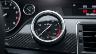
Choosing the right oil pressure gauges is not a simple matter of comparing dial sizes or advertised prices. In engine rooms, workshops, and mobile equipment, a gauge must remain readable beside vibration, heat, oil mist, and poor lighting. A needle that sticks during cold startup can hide a serious lubrication problem. Small details matter.
Industry data supports this wider view. Grand View Research identifies pressure monitoring as an important part of the global sensor industry, driven by automotive, manufacturing, energy, and process-control applications. MarketsandMarkets also reports continued growth in pressure sensors, especially where equipment requires real-time condition monitoring. These reports often combine electronic sensors with mechanical instruments, so their figures should not be treated as a direct forecast for oil pressure gauges. That limitation deserves attention.
For global buyers, selection should begin with the application, not the catalog photograph. Check the pressure range, dial diameter, connection thread, wetted materials, accuracy class, temperature rating, and vibration resistance. NPT and BSP threads are not interchangeable without the correct adapter. A 0–100 psi gauge may suit a light-duty engine, while a hydraulic system needs a different range and construction. Confirm calibration documentation and traceability against recognized quality practices, such as ISO 9001-based manufacturing controls. Also review ingress protection, chemical compatibility, and regional conformity requirements before purchase.
The “top” gauge is rarely universal. It is the gauge that delivers stable readings in a defined operating environment. Price still matters. But a cheaper instrument may create higher maintenance costs. This introduction compares practical specifications, supplier reliability, and evidence from established industry reports, while acknowledging that published market data cannot replace field testing.
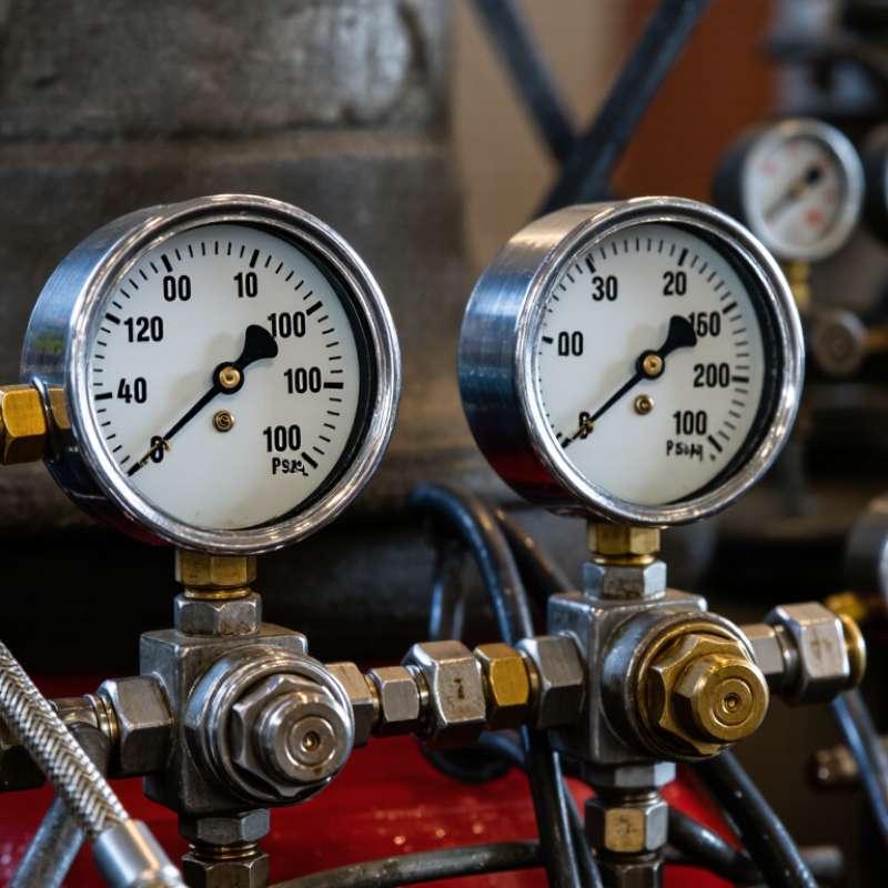
A 0–100 psi oil pressure gauge suits many automotive and industrial systems. Its metric counterpart, 0–7 bar, reaches approximately 101.5 psi. These ranges are nearly equivalent, but the dial markings differ. Choose a scale that keeps normal readings near the middle, not at the far edge. A gauge rated too high may hide small pressure changes. A gauge rated too low may suffer over-range damage.
Oil temperature, vibration, thread size, and fluid compatibility also affect reliability. Mechanical gauges connect directly to the pressure source, while electrical gauges use a sender and wiring. Both can perform well when installed correctly. Check the engine or equipment specification before selecting the sensing range. Calibration matters. A simple comparison with a certified reference gauge can reveal drift, especially after long service. I have seen installation details create more errors than the gauge itself. That part is often overlooked.
Tips: Confirm whether the system uses psi, bar, or both. Keep the pressure line short and properly supported. Use a suitable seal method without blocking the port. Inspect the pointer during startup and shutdown. Sudden movement, fogging, or a steady zero reading needs investigation. No gauge choice is perfect. A clear scale, correct range, and careful installation usually matter more than appearance.
Accuracy classes are easy to misread. Under ASME B40.100-2022 and EN 837-1 conventions, accuracy usually refers to percentage of full-scale span. A 0–100 psi gauge rated ±1% may vary by ±1 psi across its range. A ±1.6% gauge allows ±1.6 psi, while a ±2.5% gauge allows ±2.5 psi. On a 0–1,000 psi gauge, those limits become ±10, ±16, and ±25 psi. That difference is significant near a narrow operating point.
Consider a pump running at 100 psi on a 1,000 psi gauge. A ±2.5% instrument could legally indicate about 75–125 psi before other effects. That is not a small visual error. NIST Technical Note 1297 explains that measurement uncertainty includes more than the instrument rating. Temperature, mounting position, vibration, and calibration conditions also matter. Real installations are messier. Pressure pulsation can make a precise dial look unreliable.
For critical monitoring, ±1% is usually easier to justify when the operating range stays near the middle of the span. ±1.6% can balance cost and dependable control for general industrial service. ±2.5% may suit basic indication, especially where pressure changes are broad and consequences are limited. I would not select by accuracy alone. A badly ranged ±1% gauge can perform worse than a properly ranged ±2.5% gauge. Calibration records should state the reference standard, test points, temperature, and observed error, following ISO/IEC 17025 principles. That detail is often missing.
For global buyers, oil pressure monitoring usually comes down to Bourdon tubes versus electronic sensors. A Bourdon gauge uses a curved metal tube that flexes as oil pressure rises. It needs no electrical power and gives a direct mechanical reading. That simplicity can be valuable in older engines, remote equipment, and harsh repair environments. However, long capillary lines may leak, vibrate, or restrict installation.
Electronic sensors convert pressure into an electrical signal for a dashboard, data logger, or engine controller. They usually offer faster alerts, easier remote monitoring, and cleaner cabin installation. According to the MarketsandMarkets Automotive Sensors Market report, the sector was valued at approximately 28.6 billion US dollars in 2024 and is projected to reach about 40.0 billion by 2029. This growth reflects wider adoption of electronic monitoring, not automatic proof of better accuracy.
Temperature matters. A sensor beside a hot cylinder head may suffer wiring damage or calibration drift. A Bourdon mechanism can also lose accuracy after repeated vibration. The SAE J1349 engine testing standard highlights the importance of controlled pressure and temperature conditions during performance measurements. In practical inspections, buyers should compare response time, pressure range, thread compatibility, sealing method, and calibration records. Do not ignore the warning circuit. A gauge can display pressure while its sender or cable quietly fails. The choice is not perfectly clean. A certified electronic sensor suits connected machinery, while a well-calibrated Bourdon gauge remains dependable for simple, local observation.
When global buyers compare oil pressure gauges, standards matter more than a polished dial. ASME B40.100 defines performance expectations for pressure-indicating instruments, including accuracy, construction, and testing. EN 837 provides a practical European reference for gauge design, safety, and measurement behavior. These standards do not make every gauge identical. They help engineers compare evidence.
In a workshop, I check the calibration certificate, pressure range, connection material, and movement stability before approving a gauge. A 0–10 bar gauge may suit a hydraulic line, while a 0–400 bar model can hide small pressure changes. That mismatch is easy to miss. Ask whether testing followed the stated standard, not merely whether the standard appears in a datasheet. Certificates, traceable records, and clear tolerances show real competence. A certificate is useful, but it is not magic.
IP67 protection adds another useful layer. The first digit indicates strong dust protection; the second covers temporary immersion under defined conditions. It does not mean unlimited underwater operation. Gaskets, casing joints, and process connections still need inspection. Salt spray, vibration, pulsation, and hot oil can expose weak design choices. I have seen specifications look complete, yet omit temperature limits or overpressure protection. That gap deserves a direct question before purchase. Regional units and installation rules also require careful review.
Global standards reference: ASME B40.100, EN 837, and IP67 protection
Covers pressure gauge terminology, performance, construction, testing, and application guidance.
Defines requirements for mechanical pressure gauges, including design, dimensions, accuracy, and testing.
Specifies dust-tight protection and temporary immersion in water up to 1 metre for up to 30 minutes.
The chart presents the directly relevant selection dimensions for each reference. ASME B40.100 and EN 837 address pressure-gauge performance; IP67 addresses enclosure protection.
Top Oil Pressure Gauges for Global Buyers
A reliable oil pressure gauge begins with its case, thread, and calibration record. For harsh workshops, 316L stainless steel offers better resistance to salt, moisture, and many process fluids than basic steel. However, 316L is not magic. Chlorides, heat, and poor cleaning can still cause damage. Check the material certificate, not only the product description.
The connection deserves equal attention. A 1/4 NPT thread is common in North American systems, but it is not automatically interchangeable with BSP or metric threads. ASME B1.20.1 defines NPT dimensions and taper requirements. Confirm the thread standard, male or female format, and sealing method before installation. A small mismatch can leak under vibration. That is an expensive lesson.
Calibration data separates a professional instrument from a convenient-looking dial. Request the measurement range, accuracy class, test points, calibration date, reference standard, and measurement uncertainty. ISO/IEC 17025 guidance supports traceable laboratory competence, while NIST Technical Note 1297 explains why uncertainty belongs with reported results. ASME B40.100 also provides established requirements for pressure gauges. A certificate showing only “passed” is incomplete. I would prefer readings at zero, mid-scale, and full scale. Even then, I would recheck the gauge after transport, because shipping shock is often underestimated.
| Buyer Checkpoint | Recommended Requirement | Technical Data | Verification Evidence |
|---|---|---|---|
| Case material | 316L stainless steel case | Corrosion-resistant austenitic stainless steel; material designation UNS S31603 / EN 1.4404 is commonly used for 316L | Material certificate or supplier declaration identifying 316L / UNS S31603 / EN 1.4404 |
| Process connection | 1/4-18 NPT male connection | American National Standard Taper Pipe Thread; 1/4 NPT has 18 threads per inch under ASME B1.20.1 | Thread gauge inspection, dimensional drawing, and connection material specification |
| Pressure range selection | Select a full-scale range approximately 2 times the normal operating pressure where practical | Example ranges: 0–30 psi / 0–2.07 bar; 0–60 psi / 0–4.14 bar; 0–100 psi / 0–6.90 bar; 0–160 psi / 0–11.03 bar; 0–300 psi / 0–20.68 bar | Application pressure profile showing normal, maximum, and possible surge pressure |
| Accuracy class | Accuracy of ±1.0% of span or better for general industrial measurement | For a 0–100 psi gauge, ±1.0% of span equals ±1 psi across the specified calibration range | Calibration certificate stating accuracy basis, test points, reference standard, and uncertainty |
| Dial and units | Dual scale in psi and bar for international purchasing | 1 bar = 14.5038 psi; dial graduations should be clear and readable at the installation distance | Dial artwork or sample showing scale range, units, zero position, and graduation value |
| Wetted parts | 316L stainless steel Bourdon tube and socket when oil compatibility and corrosion resistance are priorities | Wetted material must be compatible with the oil type, additives, temperature, and pressure | Wetted-parts list and chemical compatibility statement |
| Overpressure protection | Specify allowable static pressure and short-term overpressure separately | Do not assume the maximum dial value equals the permitted surge pressure; values depend on the gauge design and applicable standard | Published pressure ratings and test report for static and overpressure performance |
| Temperature conditions | Declare ambient, process, and storage temperature limits | Temperature changes can affect indication accuracy; a diaphragm seal or cooling element may be required for high-temperature oil service | Temperature rating, error coefficient, and installation instructions |
| Vibration and pulsation | Use a liquid-filled case or pulsation dampener when the system has pump vibration or rapid pressure cycling | Glycerin-filled designs can improve pointer stability and reduce mechanical wear, but fill-fluid temperature limits must be checked | Fill-fluid specification, vibration rating, and pulsation-service recommendation |
| Calibration traceability | Calibration traceable to national or international measurement standards | Certificate should identify the reference instrument, serial number, calibration date, environmental conditions, and uncertainty | Individual calibration certificate supplied with each gauge or batch |
| Applicable standard | Require conformity to a recognized pressure-gauge standard | ASME B40.100 is widely used for indicating pressure gauges; thread dimensions should reference ASME B1.20.1 | Declaration of conformity, test report, or standard reference on the technical datasheet |
| Test Point | Reference Pressure | Equivalent Pressure | Acceptance Limit at ±1.0% Span | Required Record |
|---|---|---|---|---|
| 0% span | 0 psi | 0 bar | ±1 psi | As-found and as-left readings |
| 25% span | 25 psi | 1.72 bar | 24–26 psi | Increasing and decreasing readings |
| 50% span | 50 psi | 3.45 bar | 49–51 psi | Repeatability and hysteresis data |
| 75% span | 75 psi | 5.17 bar | 74–76 psi | Reference standard identification |
| 100% span | 100 psi | 6.90 bar | 99–101 psi | Calibration date, uncertainty, and technician identification |
Note: The calibration values above are a standardized example of the information a buyer should request. Actual acceptance limits must follow the ordered gauge accuracy class, applicable standard, and purchase specification.
3295 Cobb International Blvd.
Kennesaw, GA 30152
800-367-1377
sale@patiostools.com
© 2023 - Marsh Instruments