How to Choose Differential Pressure Gauges in 2026?
Choosing differential pressure gauges in 2026 starts with understanding what the measurement must tell you. A gauge may monitor a filter, compare pressure across a pump, or help operators spot changing conditions in a process line. The right choice depends on the application, not just the price or dial size.
Define the expected pressure range before comparing models. A filter that normally shows a small pressure difference may need a more sensitive range than a system with larger pressure swings. Then check the required accuracy, operating temperature, vibration, and whether the process fluid can contact the gauge’s wetted materials. Stainless steel may suit many demanding environments, but compatibility must be confirmed against the actual fluid and conditions. Small details matter.
Installation deserves equal attention. Confirm the connection size, mounting position, available space, and whether the gauge needs isolation valves or a protective enclosure. In field use, poor visibility or a hard-to-reach dial can make a technically suitable instrument frustrating to read. Calibration and maintenance requirements also affect long-term reliability. Ask how the device will be checked, and how easily it can be replaced.
Specifications can look reassuring on paper. They do not always reflect real operating conditions. Even experienced teams can overlook pulsation, contamination, or frequent cleaning when selecting a model; that assumption deserves a second look. This guide explains how to compare key features, interpret manufacturer data, and match a differential pressure gauge to its intended service. The goal is a dependable reading, not simply a gauge that fits the pipe.
Define the Medium, Normal ΔP, and Static Pressure Before Selecting a Gauge
How to Choose Differential Pressure Gauges in 2026?
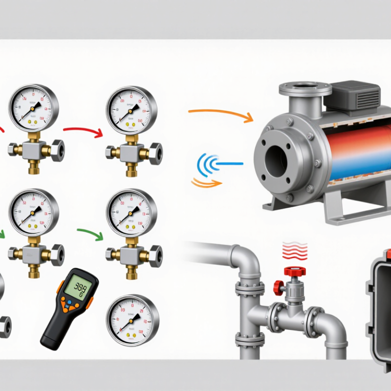
Define the medium, normal differential pressure (ΔP), and static pressure before comparing gauge ranges. Record whether the process fluid is clean, corrosive, viscous, or prone to crystallizing. These details affect wetted materials, seals, and whether impulse lines may clog. Static pressure is the line pressure acting on both sides of the sensing element; it is not the same as ΔP. A gauge may tolerate the expected differential yet fail under excessive static pressure or a sudden pressure spike.
Then estimate the normal ΔP and its likely peaks. Choose a range that keeps routine readings clear without leaving too little headroom for process changes. ASME B40.100 expresses pressure-gauge accuracy as a percentage of span: on a 0–100 kPa gauge, ±1% of span equals ±1 kPa. At a normal reading of 10 kPa, that is 10% of the reading. A small calculation, but an easy one to miss.
For flow applications, check that the gauge suits the primary element and installation conditions described in ISO 5167-2:2022; the standard addresses differential-pressure measurement using orifice plates. Confirm maximum static pressure, overpressure limits, connection orientation, and temperature separately. Field readings can drift when impulse lines collect liquid or gas, even with a correctly selected gauge. That part is easy to underestimate. Recheck the actual operating range after startup, because design values do not always match the process.
How to Choose Differential Pressure Gauges in 2026
Define the medium, normal differential pressure (ΔP), and maximum static pressure before selecting a gauge. The examples below show normal ΔP alongside an illustrative full-scale gauge range.
Example conditions: Water filter — normal ΔP 6 kPa, static pressure 1.0 MPa; compressed-air filter — normal ΔP 18 kPa, static pressure 0.8 MPa; water strainer — normal ΔP 70 kPa, static pressure 1.6 MPa. These are illustrative operating examples, not a universal sizing rule. Confirm medium compatibility, expected pressure peaks, accuracy needs, and the gauge’s rated static pressure with its manufacturer.
Choose a Full-Scale Range That Places Normal ΔP Near 50% of Span
How to Choose Differential Pressure Gauges in 2026?
Choose a Full-Scale Range That Places Normal ΔP Near 50% of Span
Choose a differential pressure gauge so its normal operating reading falls near the middle of the scale. ASME B40.100 guidance favors operating pressure in the middle third of a gauge’s range. A midpoint target gives useful room for both rising and falling pressure. It also avoids crowding the pointer near either end. For example, if a filter normally runs at 6 psi differential, a 0–12 psi range places that reading at 50% of span.
Full-scale accuracy makes range selection matter. With a hypothetical specification of ±1% of full scale, a 0–12 psi gauge has an error of ±0.12 psi. At a 6 psi reading, that equals ±2% of the reading. A 0–30 psi gauge with the same specification has ±0.30 psi error, or ±5% at 6 psi. Check whether the actual instrument specifies accuracy as a percentage of span, reading, or both. Real systems fluctuate, and the midpoint rule may need adjustment.
Tips: Record clean-filter and loaded-filter ΔP during commissioning. Pick a range that keeps routine readings near 50% while leaving headroom for expected peaks. If routine readings sit low, reconsider the range—not just the dial size.
Compare Accuracy: ±1.0% FS Means ±0.1 Unit on a 10-Unit Range
How to Choose Differential Pressure Gauges in 2026?
Accuracy should be read against full scale, not the displayed value. A gauge rated at ±1.0% FS with a 10-unit range allows ±0.1 unit error. At a 5-unit reading, that error equals 2% of the reading. This distinction matters when monitoring low-flow filters or narrow pressure drops. ASME B40.100-2022 highlights accuracy classification, while NIST Technical Note 1297 explains how measurement uncertainty should be evaluated and reported. These references support a practical rule: choose a range that covers the process, but avoid excessive span.
Do not size a 0–100-unit gauge for a normal 8-unit signal. Its ±1.0% FS tolerance may become ±1 unit. That can hide a serious process change. Field checks also show why temperature, vibration, pulsation, and zero drift deserve attention. A gauge can meet its laboratory specification and still behave poorly beside a hot pump. This is the imperfect part of selection. Real installation conditions often matter more than a neat catalog number.
Tips: Keep normal operation near the middle third of the scale. Confirm whether accuracy includes hysteresis and repeatability. Request calibration data with traceability to national standards. For unstable lines, add a snubber or suitable dampening device. Record ambient temperature during verification. One more detail: if the process limit is tight, calculate uncertainty before purchasing. A ±0.1-unit error may look small, but it can change a maintenance decision.
How to Choose Differential Pressure Gauges in 2026? — Compare Accuracy: ±1.0% FS Means ±0.1 Unit on a 10-Unit Range
| Accuracy Rating (% of Full Scale) |
Example Full-Scale Range |
Maximum Error at Full Scale |
Maximum Error at a 2-Unit Reading |
Practical Selection Note |
| ±0.25% FS |
0 to 10 units |
±0.025 units |
±0.025 units (±1.25% of the reading) |
Consider when tight measurement tolerance is important and the instrument’s specifications support the required operating conditions. |
| ±0.5% FS |
0 to 10 units |
±0.05 units |
±0.05 units (±2.5% of the reading) |
A more precise option than ±1.0% FS; compare its cost and calibration requirements with the process tolerance. |
| ±1.0% FS |
0 to 10 units |
±0.1 units |
±0.1 units (±5% of the reading) |
At a 10-unit full scale, 1.0% of full scale is 0.1 unit—not 1.0% of the current reading. |
| ±1.5% FS |
0 to 10 units |
±0.15 units |
±0.15 units (±7.5% of the reading) |
May be suitable where the allowable process error is wider; verify the instrument’s stated accuracy definition. |
| ±2.5% FS |
0 to 10 units |
±0.25 units |
±0.25 units (±12.5% of the reading) |
Assess carefully for low readings, where a fixed full-scale error can be a large share of the measured value. |
Calculation: Maximum error = accuracy percentage × full-scale value. For ±1.0% FS on a 0–10-unit range: 0.01 × 10 = ±0.1 unit. These are illustrative calculations; confirm the specified accuracy, range, units, and operating conditions for the gauge being evaluated.
Check Static-Pressure and Overrange Ratings Against Process Peaks
How to Choose Differential Pressure Gauges in 2026?
Static pressure and overrange ratings deserve more attention than dial size. A differential gauge may read only 2 bar, yet each port could face 25 bar. Check both values separately. ASME B40.100 requires pressure instruments to state pressure limits, accuracy, and service conditions clearly. Do not treat the differential range as the body rating.
Start with the process peak, not the normal operating point. Record startup surges, blocked lines, valve closures, pump trips, and steam hammer. A line normally operating at 4 bar may briefly reach 12 bar. Select a static-pressure rating above that peak, with a practical safety margin. Then verify overrange protection for the worst pressure imbalance. A 2024 pressure-instrument market analysis from MarketsandMarkets identifies process safety and predictive maintenance as major selection drivers. Yet market trends cannot replace site measurements. A neat datasheet can still hide a bad assumption.
Tips: Write down maximum pressure at each port. Ask for peak duration, not only peak value. Compare the gauge rating with relief-valve settings. NIST Technical Note 1297 recommends reporting measurement uncertainty with a stated confidence level; k=2 commonly represents about 95% coverage. Include that uncertainty when judging a narrow differential range. Field engineers should also inspect impulse lines after installation. Clogged tubing can show a calm reading while the process is unstable. That is easy to miss.
Verify Wetted Materials, Connections, and Applicable ASME B40.100 Guidance
How to Choose Differential Pressure Gauges in 2026?
Wetted materials deserve the first inspection. A stainless-steel case does not guarantee compatible internal parts. Check the diaphragm, seals, body, and fill fluid against the process medium, concentration, temperature, and cleaning chemicals. Chlorides, acids, and high-purity fluids can expose weak material choices quickly. Request a complete wetted-materials statement, not a general “corrosion-resistant” claim.
Connections also need practical verification. Confirm thread type, size, pressure rating, orientation, and access for calibration. NPT and BSP threads are not interchangeable, even when they appear similar. ASME B40.100 provides recognized guidance for pressure-gauge terminology, performance, testing, safety, and application. It should support selection, not replace engineering judgment. The standard does not remove the need to verify process compatibility.
Small errors become expensive. The U.S. Department of Energy’s Improving Compressed Air System Performance sourcebook reports that leaks can waste 20–30% of compressor output. Poorly selected differential gauges may hide filter blockage or create false maintenance signals. Choose a readable range, suitable accuracy, and connection layout that avoids pulsation and vibration. I would also document the reasoning. That step is often skipped. Recheck it. Conditions change, and old assumptions can remain in drawings for years.